
Chemical liquid processing apparatus for processing a substrate and the method thereof

a technology of chemical liquid and processing apparatus, which is applied in the direction of chemistry apparatus and processes, cleaning equipment, coatings, etc., can solve the problems of reducing the etching velocity in the etching region near a broader etching region, not accelerating the supply of new etching etchants to the etching region, and difficulty in suppressing the etching velocity

Inactive Publication Date: 2003-06-17
KK TOSHIBA
View PDF8 Cites 25 Cited by
  • Summary
  • Abstract
  • Description
  • Claims
  • Application Information

AI Technical Summary

Benefits of technology

This approach improves processing uniformity, reduces pattern fall, and prevents dust generation, thereby enhancing the yield rate of chemical liquid processing by ensuring effective etching and drying without substrate rotation.

Problems solved by technology

First, technical problems in the chemical liquid film forming step will be described.
The chemical liquid film forming step for etching the processing object film by coating and settling the chemical liquid on the processing object substrate, on which the processing object film is formed, has such a problem that supply of new etchant to an etching region is not accelerated because etching product remains on the etching region and the surrounding of the etching region.
This problem is particularly conspicuous around the etching region near a broader etching region.
However, if such technology is employed, after the chemical liquid is agitated, the sheet material needs to be washed and when washing the sheet material, dust and dirt adhering to the sheet material adhere to the surface of the processing object substrate, so that a defect may occur on the processing object substrate.
Therefore, even if this technology is employed, the reduction of etching velocity in the etching region near a broader etching region must be difficult to suppress sufficiently.
As described above, the conventional chemical liquid film forming step cannot suppress the reduction of etching velocity in the etching region without generation of defects or additional work.
Thus, the yield rate of the entire chemical liquid processing cannot be improved.
However, when the liquid removing (cleaning / drying) step is carried out by this method, the quantity of defects induced by microscopic dust generated from abrasion between a chuck for fixing the substrate and a rear face of the substrate is increased with decrease of pattern dimension and increase of rotation speed.
Thus, in the conventional liquid removing (cleaning / drying) step, the yield rate of the entire chemical liquid processing cannot be improved like the chemical liquid film forming step.
As described above, the conventional chemical liquid processing apparatus and chemical liquid processing method have technical problems which should be solved early in both the chemical liquid film forming step and liquid removing (cleaning / drying) step.
Thus, it is difficult to improve the yield rate of the entire chemical liquid processing.

Method used


Image

  • Chemical liquid processing apparatus for processing a substrate and the method thereof
  • Chemical liquid processing apparatus for processing a substrate and the method thereof
  • Chemical liquid processing apparatus for processing a substrate and the method thereof

Examples


first embodiment

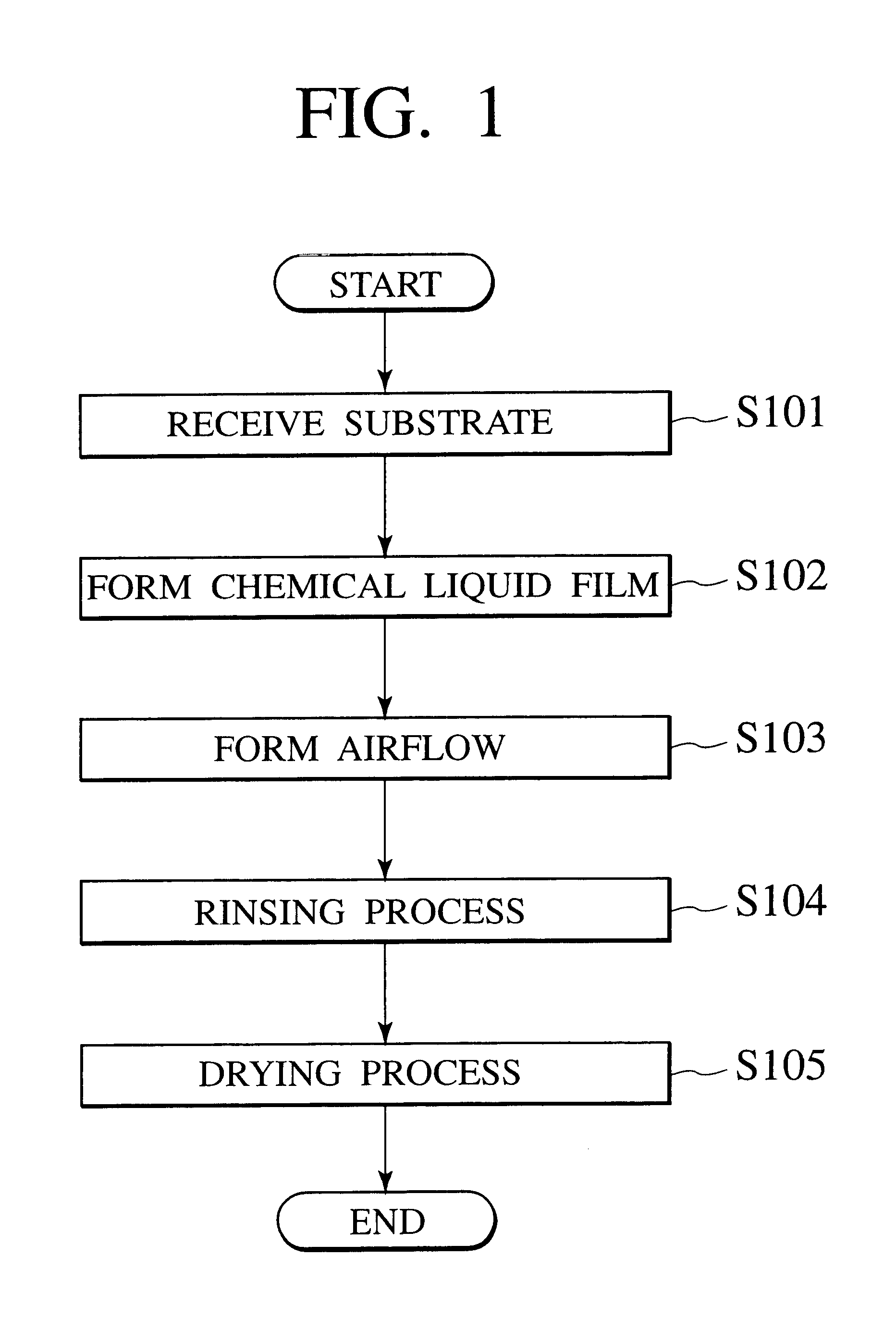
First, chemical liquid processing method according to the present invention is explained with reference to FIGS. 1-4.

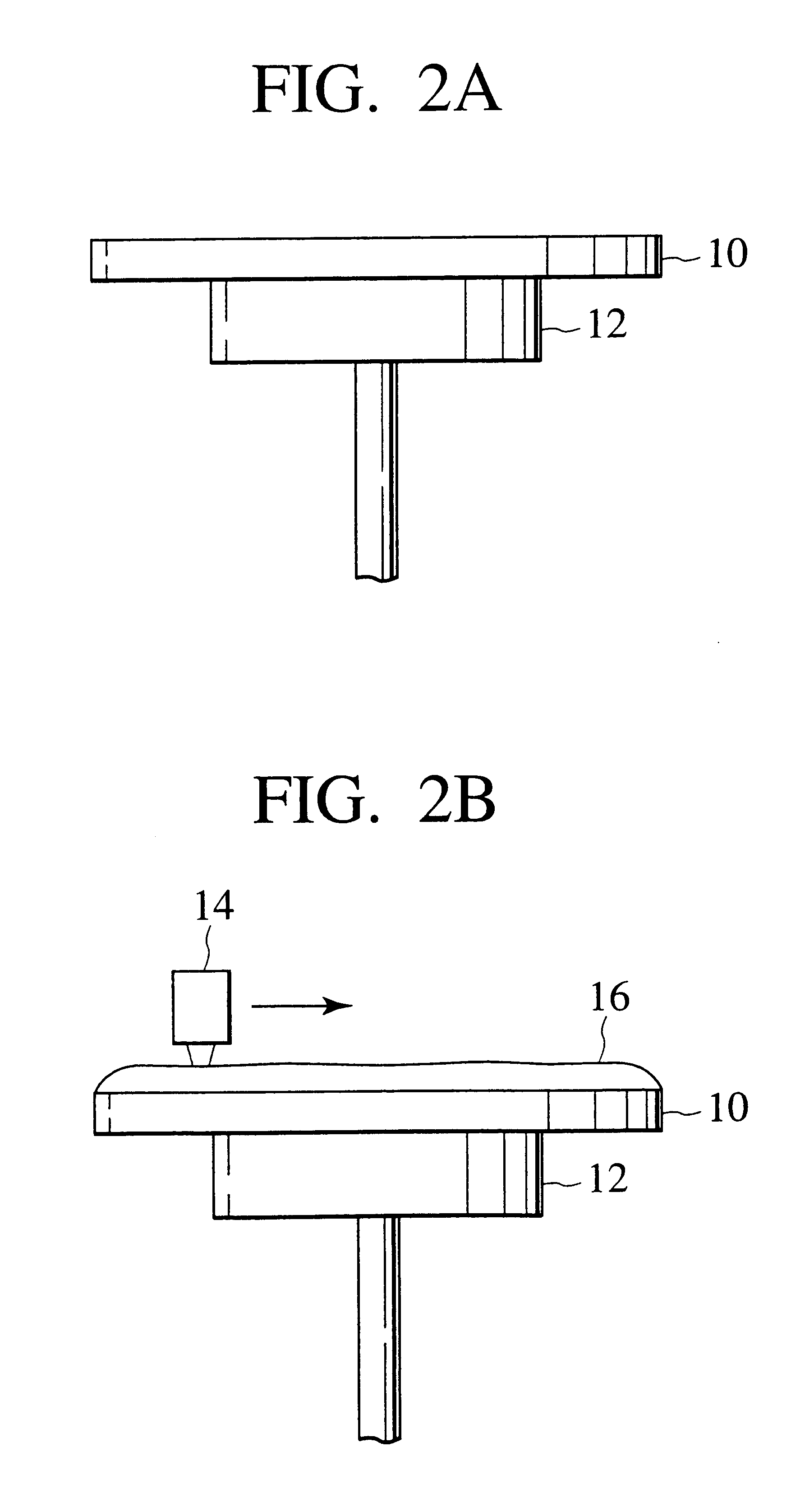
(1) First, as shown in FIG. 2A, the processing object substrate 10 which preparing step is finished is carried to the top of the substrate holding portion 12 by means of a transportation robot (not shown). And, the processing object substrate 10 is left from the transportation robot and received by the substrate holding portion 12. The processing object substrate 10 is fixed to the substrate holding portion 12 by sucking (S101).

(2) Next, as shown in FIG. 2B, chemical liquid 16 for processing a processing object film on the processing object substrate 10 is formed on the processing object substrate 10. Chemical liquid 16 is supplied from, for example, the chemical spouting nozzle 14 disposed above the processing object substrate 10. The chemical spouting nozzle 14 scans the processing object substrate 10 from an end of the processing object substrate 10 to the other en...

second embodiment

Next, the chemical liquid processing according to the second embodiment of the present invention is described.

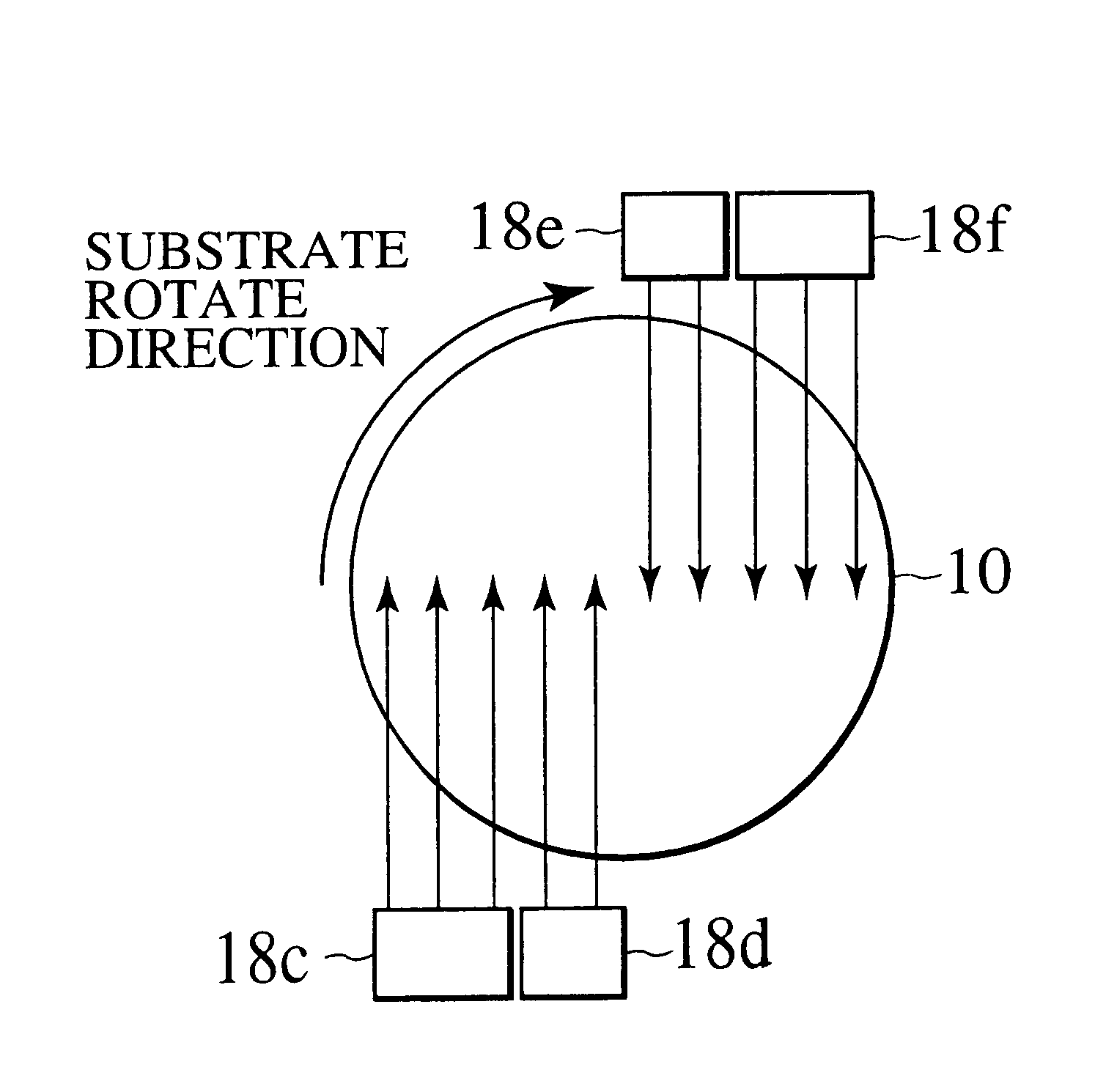
Although air flow is formed above the film of the chemical liquid 16 by supplying gas from the gas supply portion 18 disposed near the outer periphery of the processing object substrate 10 according to the first embodiment of the present invention, in the second embodiment of the present invention, air flow is formed by a rotation of a plate disposed above the film of the chemical liquid 16. Referring FIG. 1, FIG. 9.about.FIG. 11, the chemical liquid processing method according to the second embodiment of the present invention is explained below.

(1) First, as shown in FIG. 9A, the processing object substrate 10 which preparing step is finished is carried to the top of the substrate holding portion 12 by means of a transportation robot (not shown). Then, the processing object substrate 10 is left from the transportation robot and received by the substrate holding portion 12. ...

third embodiment

Next, the chemical liquid processing according to the third embodiment of the present invention is explained.

Although gas supplied above the film of the chemical liquid 16 by the gas supply portion 18 is restricted to only inactive gas such as nitrogen gas according to the first embodiment, in the third embodiment of the present invention, the other gas such as ozone is added. The third embodiment of the present invention is explained below referring the result of the experiment which the inventors performed.

First, reflection preventing film of 6 nm and resist film of 400 nm were formed successively on a semiconductor substrate 10, which was the processing object substrate. Then, after a latent image was formed on a resist film using an exposure device, baking was carried out at 130.degree. for 60 seconds.

Next, developing solution 16, which was the chemical liquid, was supplied to the top of a semiconductor substrate 10 so as to form film of the developing solution 16 by puddling on...


PUM


Abstract

In this disclosure, air flow is formed above chemical liquid film and a move of the chemical liquid is generated by making the air flow into a contact with the surface of chemical liquid. Further, a negative pressure is generated in a space between a processing object substrate and a plate by rotating the plate. Consequently, uniformity of processing of chemical liquid is improved, so that liquid removing step can be carried out effectively. As a result, yield rate of chemical liquid treatment can be improved.

Description

The subject application is related to subject matter disclosed in the Japanese Patent Applications No. Tokugan 2000-039683 filed in Feb. 17, 2000, and No. Tokugan 2000-297441 filed in Sep. 28, 2000 in Japan, to which the subject application claims priority under the Paris Convention and which is incorporated by reference herein.1. Field of the InventionThe present invention relates to a chemical liquid processing apparatus for processing a substrate using chemical liquid and a chemical liquid processing method therewith and more particularly to technology for processing various types of substrates such as a semiconductor substrate in semiconductor device manufacturing process, reticule (photo mask) in lithographic process which is one step of semiconductor device manufacturing process, and flat panel in liquid crystal display manufacturing process.2. Description of the Related ArtGenerally, chemical liquid processing for processing various types of substrates using chemical liquid i...

Claims


Application Information

Patent Timeline
Patent Type & Authority Patents(United States)
IPC IPC(8): B05C11/06B05C11/02B05D1/00B05C11/08B05D3/04
CPCB05C11/06B05D1/005H01L21/67034H01L21/6708B05C11/08Y10S438/906Y10S134/902B05D3/0406
Inventor ITO, SHINICHI
Owner KK TOSHIBA
Learn More