

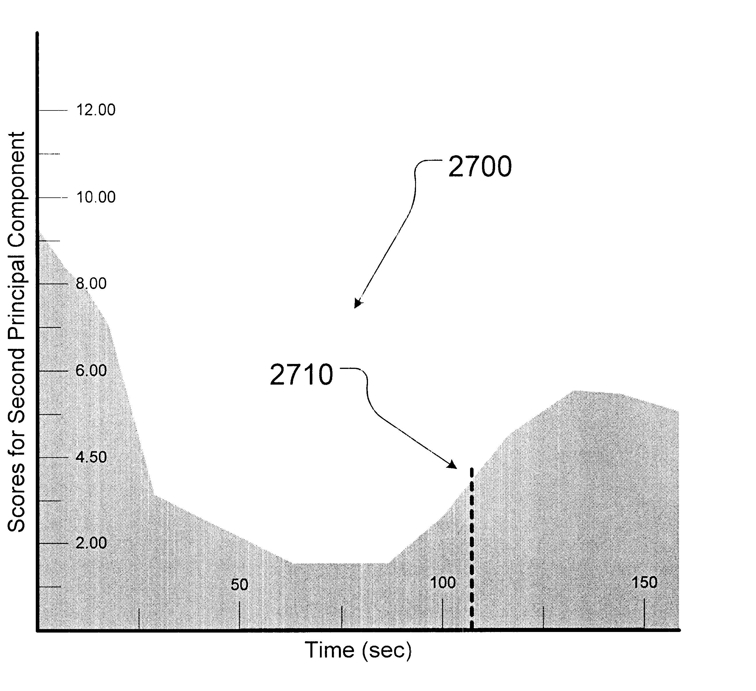
Method of determining etch endpoint using principal components analysis of optical emission spectra
a technology of optical emission spectra and endpoint determination, which is applied in the direction of antibody medical ingredients, peptide sources, program control, etc., can solve the problems of difficulty, inability to know the wavelength in the spectrum to monitor, and general availability of specific wavelength information
- Summary
- Abstract
- Description
- Claims
- Application Information
AI Technical Summary
Problems solved by technology
Method used
Image

Examples
Embodiment Construction
Illustrative embodiments of the invention are described below. In the interest of clarity, not all features of an actual implementation are described in this specification. It will of course be appreciated that in the development of any such actual embodiment, numerous implementation-specific decisions must be made to achieve the developers' specific goals, such as compliance with system-related and business-related constraints, which will vary from one implementation to another. Moreover, it will be appreciated that such a development effort might be complex and time-consuming, but would nevertheless be a routine undertaking for those of ordinary skill in the art having the benefit of this disclosure.
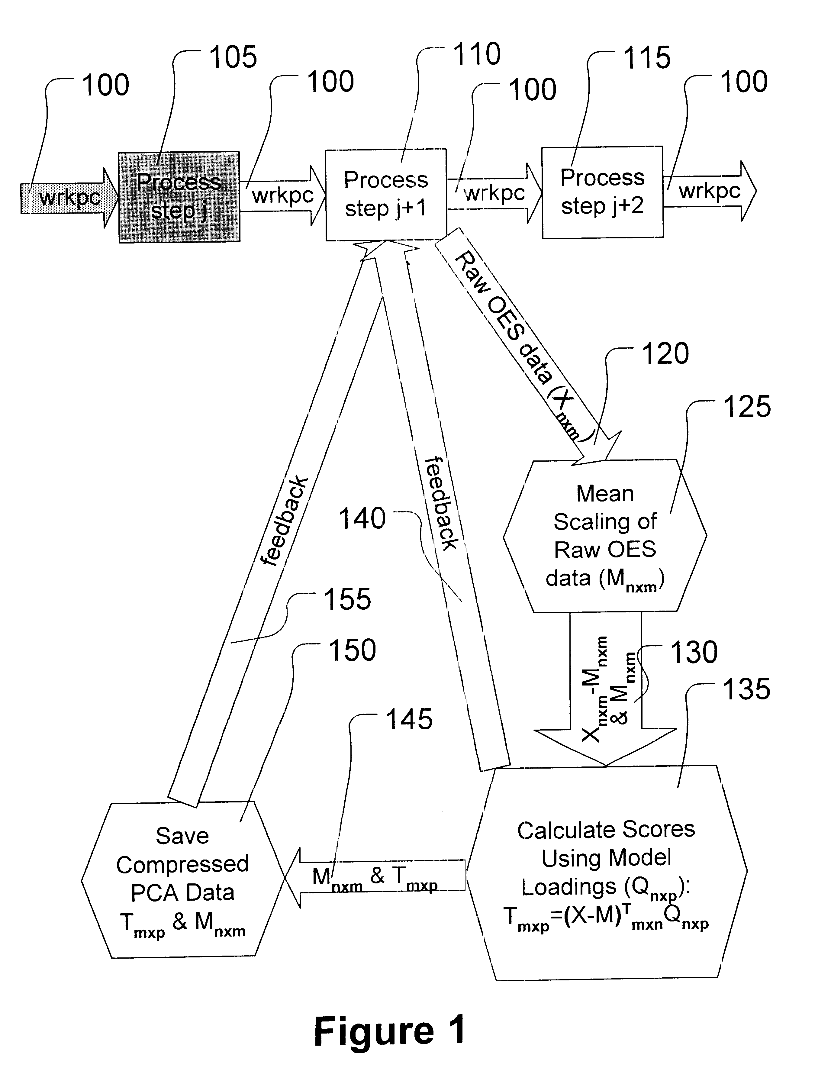
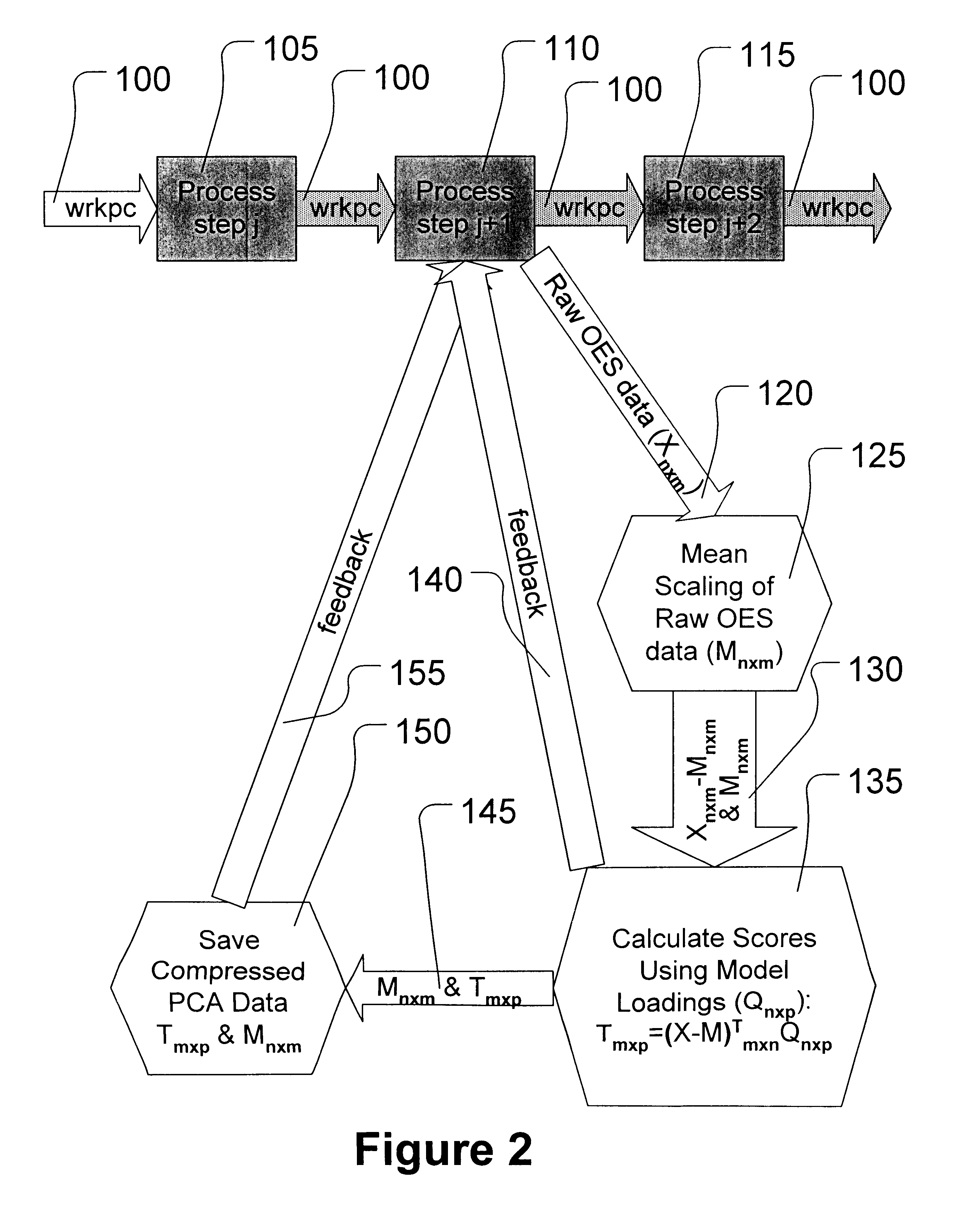
Using optical emission spectroscopy (OES) as an analytical tool in process control (such as in etch endpoint determination) affords the opportunity for on-line measurements in real time. A calibration set of OES spectra bounding the acceptable process space within which a particular pr...
PUM
| Property | Measurement | Unit |
|---|---|---|
| wavelength | aaaaa | aaaaa |
| wavelengths | aaaaa | aaaaa |
| spectral wavelengths | aaaaa | aaaaa |
Abstract
Description
Claims
Application Information