Portable digital lidar system

a lidar and digital technology, applied in the field of can solve the problems of inability to discriminate between biological weapon (bw) agent aerosols and other natural or interferent aerosol clouds, lack of specificity of elastic scattering technique for deterministic application of data in the battle field, and inability to provide in-the-field, portable early warning detection systems

Inactive Publication Date: 2003-07-15
SCI & ENG SERVICES
View PDF1 Cites 89 Cited by
  • Summary
  • Abstract
  • Description
  • Claims
  • Application Information

AI Technical Summary

Benefits of technology

Another object of the present invention is to integrate multiple analysis techniques into a detection system to reduce a probability of false alarms.
Thus, the PDL lidar sensor of the present invention is well-suited for biological standoff detection. The sensor addresses the requirements of high sensitivity and autonomous operation capability, eye-safety, and the ability to operate during the day for long-range detection. Importantly, these attributes are complemented with small size, rugged packaging, low power and maintenance requirements, and low cost.

Problems solved by technology

However, single wavelength aerosol lidars, as currently employed, do not provide discrimination between biological weapon (BW) agent aerosols and other natural or interferent aerosol clouds.
However, the elastic scattering technique lacks the required specificity for deterministic application of the data in the battle field.
However, present technologies, owing to the complexity and laser power levels required for fluorescence and aerosol lidar, are limited in range and not well suited for an in-the-field, portable early warning detection system.
In addition to photon shot noise generated by the laser scattered light falling on the detector, a detection system itself can contribute to the noise.
While the SNR of an analog lidar detector can be improved by signal averaging, increasing the PRF of a analog-suitable laser (e.g., a 100 mJ laser with a repetition rate of 30 Hz) can be relatively expensive and difficult.
However, the 1.5 .mu.m laser is a complex system requiring the 1.06 .mu.m Nd:YAG output to be down shifted in an optical parametric oscillator OPO.
Also, commonly available 1.5 .mu.m detectors are not sufficiently sensitive; hence special detectors are needed, adding to the cost and complexity of the sensing systems.

Method used


Image

  • Portable digital lidar system
  • Portable digital lidar system
  • Portable digital lidar system

Examples


Embodiment Construction

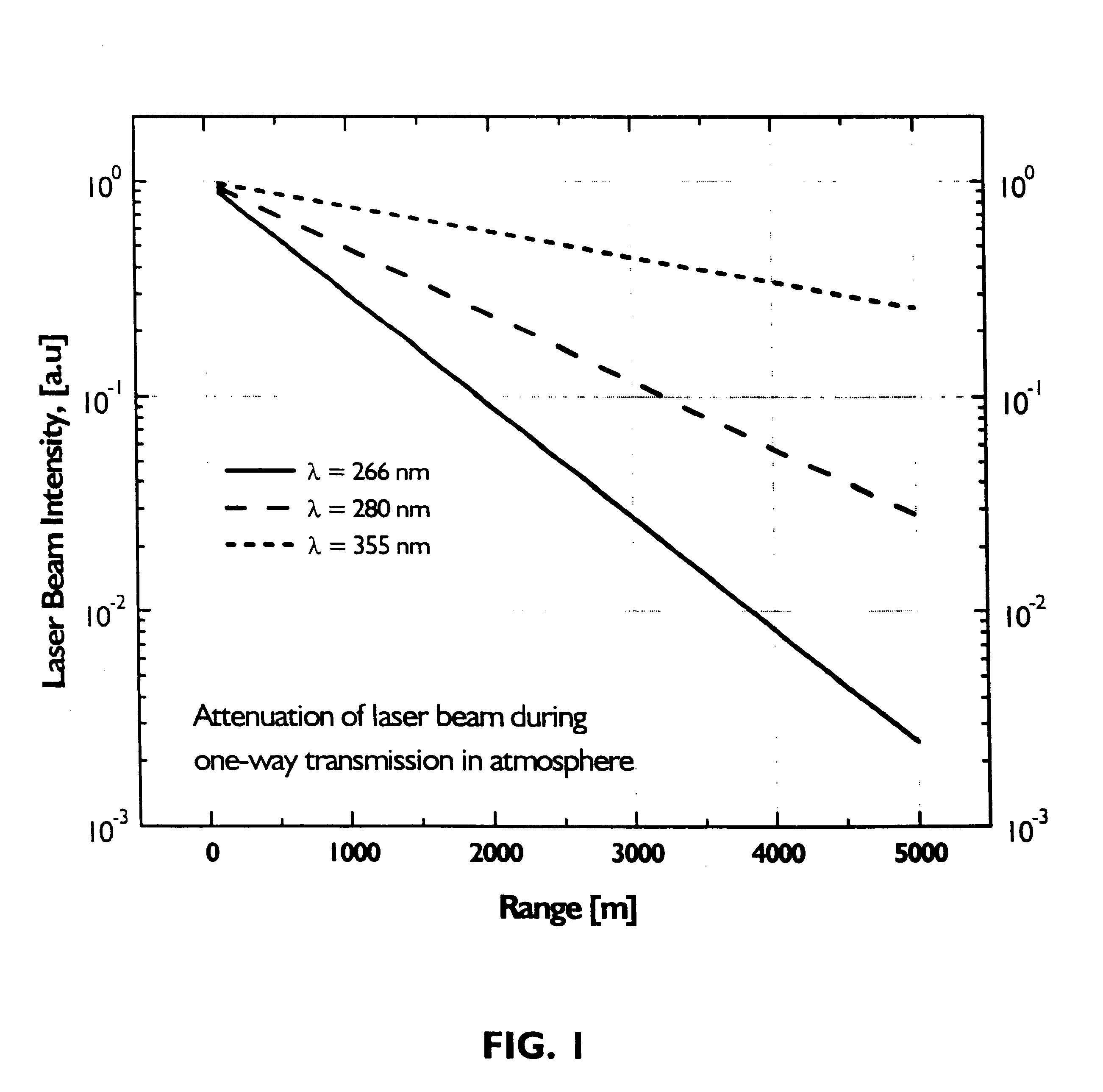
Referring now to the drawings, wherein like reference numerals designate identical or corresponding parts throughout the several views, and more particularly to FIG. 1 thereof, FIG. 1 shows at three wavelengths (i.e., 266, 280 and 355 nm) the reduction in the laser beam intensity due to scattering and absorption by atmospheric constituents as the laser beam travels to a target. According to the present invention, the difference in the fluorescence between excitation at 266 nm and 355 nm is more than compensated by the difference in the atmospheric transmittance shown in FIG. 1. From the lidar signal considerations shown in FIG. 1, even with a 100-fold smaller fluorescence cross section, the 355 nm lidar is a preferred embodiment of the present invention.

In a fluorescence lidar, autofluorescence excited by a UV laser from biological cells is utilized to identify the fluorescing biological cells from other non-biological or naturally occurring particles. Naturally fluorescent aromatic...


PUM

PropertyMeasurementUnit
wavelengthaaaaaaaaaa

Abstract

A light detecting and ranging system and method for detecting airborne agents in which the system includes a laser which provides laser pulses of at least two wavelengths, a transmitter which transmits the laser pulses, a receiver which receives both elastically backscattered signals from airborne agents and fluorescence signals from the airborne agents, a common telescope which both focuses a laser beam transmission of the laser pulse from the transmitter to a far field and receives the elastically backscattered signals and the fluorescence signals from the far field, a digital detection system having at least one of a backscatter optical detector which detects the elastically backscattered signals and a fluorescence optical detector which detects the fluorescence signals from the airborne agents.

Description

1. Field of the InventionThe present invention relates to a portable light detecting and ranging (LIDAR) system for long-range aerosol detection of biological weapon gas clouds. As such, the system can be used to provide early warning for field personnel, providing the necessary time for personnel to prepare for the arriving gas cloud.2. Discussion of the BackgroundRemote stand-off detection of chemical / biological (chem / bio) agents is considered to be a critical necessity in early warning systems enabling maximum survivability of personnel in the battlefield and other sensitive areas. Pulsed elastic backscatter lidar operating in the visible, as described by Lee, et al, "Micro Pulse Lidar for Aerosol & Cloud Measurement", Advances in Atmospheric Remote Sensing with Lidar, pp 7-10, A. Ansmann, Ed., Springer Verlag, Berlin, 1997, the entire contents of which are incorporated herein by reference, and near IR, as described by Condatore, et al, "U.S. Army Soldier and Biological Chemical ...

Claims


Application Information

Patent Timeline
Patent Type & Authority Patents(United States)
IPC IPC(8): G01N21/64G01S17/00G01S17/95G01S7/497G01S7/48G01N21/35G01N21/39
CPCG01N21/6402G01N21/6486G01S7/4972G01S17/95G01N21/3504G01N21/39Y02A90/10
Inventor LEE, HYO SANGHWANG, IN HEONPRASAD, COORG R.
Owner SCI & ENG SERVICES
Why Eureka
Try Eureka