Method and arrangement at a multiple cylinder four-stroke cycle internal combustion engine

a technology of internal combustion engine and multiple cylinders, applied in the direction of engine starters, electric control, machines/engines, etc., can solve the problems of affecting reducing the service life of the engine, so as to achieve the cycle position of the cylinder reliably and simple and safe solution

Inactive Publication Date: 2003-07-22
SCANIA CV AB
View PDF5 Cites 2 Cited by
  • Summary
  • Abstract
  • Description
  • Claims
  • Application Information

AI Technical Summary

Benefits of technology

An object of the invention is to make it possible, without recourse to camshaft sensors, to determine reliably the cycle position of a cylinder in a multiple cylinder four-stroke engine. Another object is to produce a simple and safe solution.
By ensuring that a control unit can be set correctly on each starting operation, it is possible to use various types of control units with differing characteristics together with the engine with high reliability. The superimposed interference oscillation can be made virtually imperceptible for the driver of the vehicle by virtue of its frequency harmonizing with the ordinary oscillation and by virtue of the procedure being effected briefly at the beginning of the starting operation.
The arrangement produced according to the invention can be constructed using simple components and can therefore be made simple and robust.

Problems solved by technology

However, such camshaft sensors are relatively difficult to install and to make sufficiently robust, for which reason it would be desirable for it to be possible to utilize simpler systems but still achieve good precision and reliability.
In electronic fuel injection systems, the failure of such a camshaft sensor can result in functional problems, as the possibility of determining the current cycle position is thus lost.
It has also been found to be difficult to use only flywheel sensors instead, as uncertainty arises about which of two crankshaft revolutions the engine is in at the time.
Another problem in this context is that an electronic control unit, for example in connection with being started or after a programming change or the like, cannot retain stored information about the position in which the crankshaft last stopped, but has to be synchronized with the engine again.
Such circumstances may result in the control unit misinterpreting the situation and operating in an incorrect cycle position, with attendant operating problems.

Method used


Image

  • Method and arrangement at a multiple cylinder four-stroke cycle internal combustion engine
  • Method and arrangement at a multiple cylinder four-stroke cycle internal combustion engine
  • Method and arrangement at a multiple cylinder four-stroke cycle internal combustion engine

Examples


Embodiment Construction

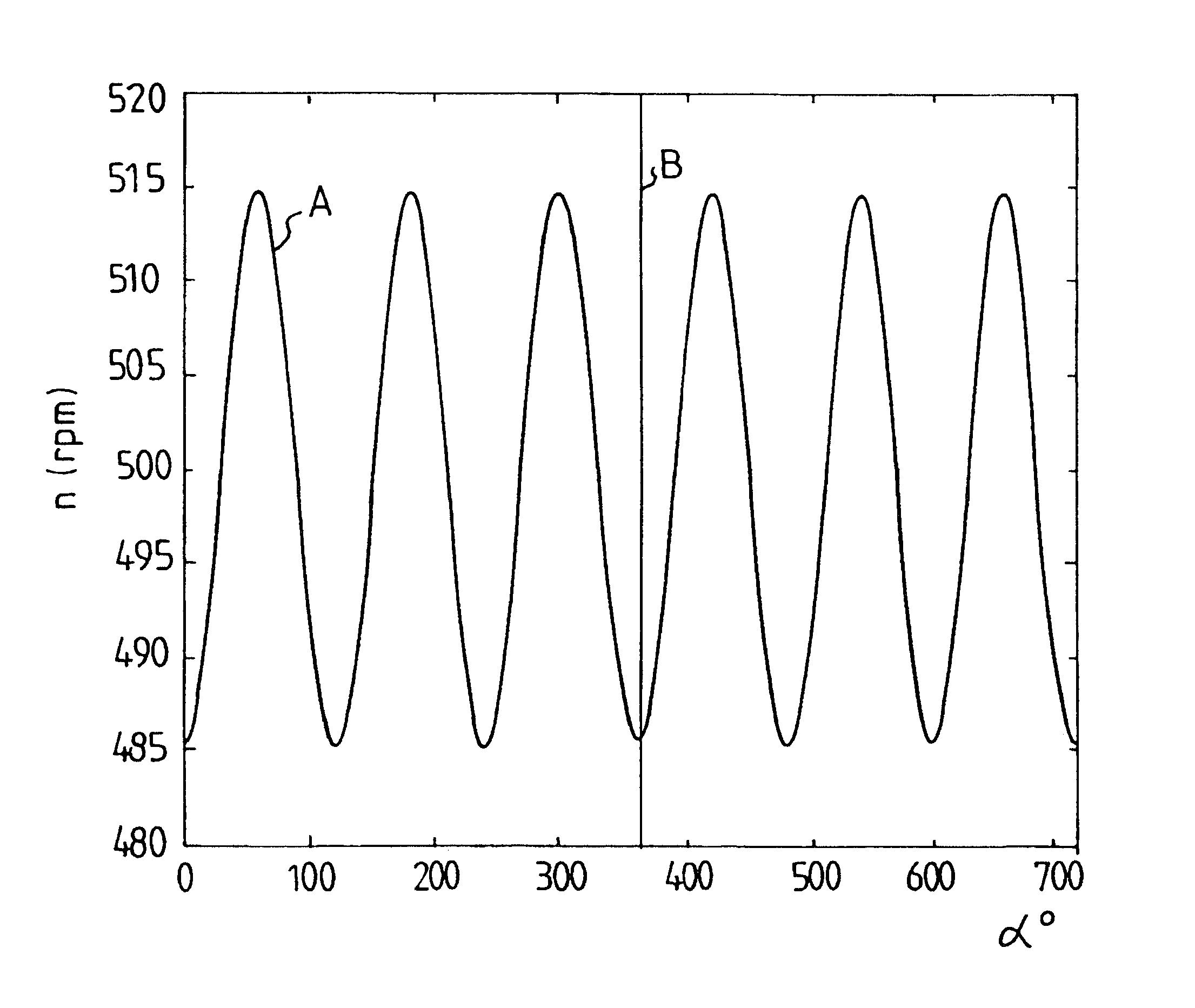
In an internal combustion engine of the four-stroke type, an operating cycle of two crankshaft revolutions is performed for each cylinder, and ignition takes place once in each cylinder every other crankshaft revolution. A larger number of cylinders therefore means a larger number of ignitions per crankshaft revolution, a 4 cylinder engine having two ignitions per crankshaft revolution, for example, while a 6 cylinder engine has three ignitions and an 8 cylinder engine has four ignitions per crankshaft revolution. In cases where this type of engine is provided with fuel injection, it is important that fuel injection and ignition in each cylinder take place when the piston of the cylinder is located in the correct phase of its operating cycle.

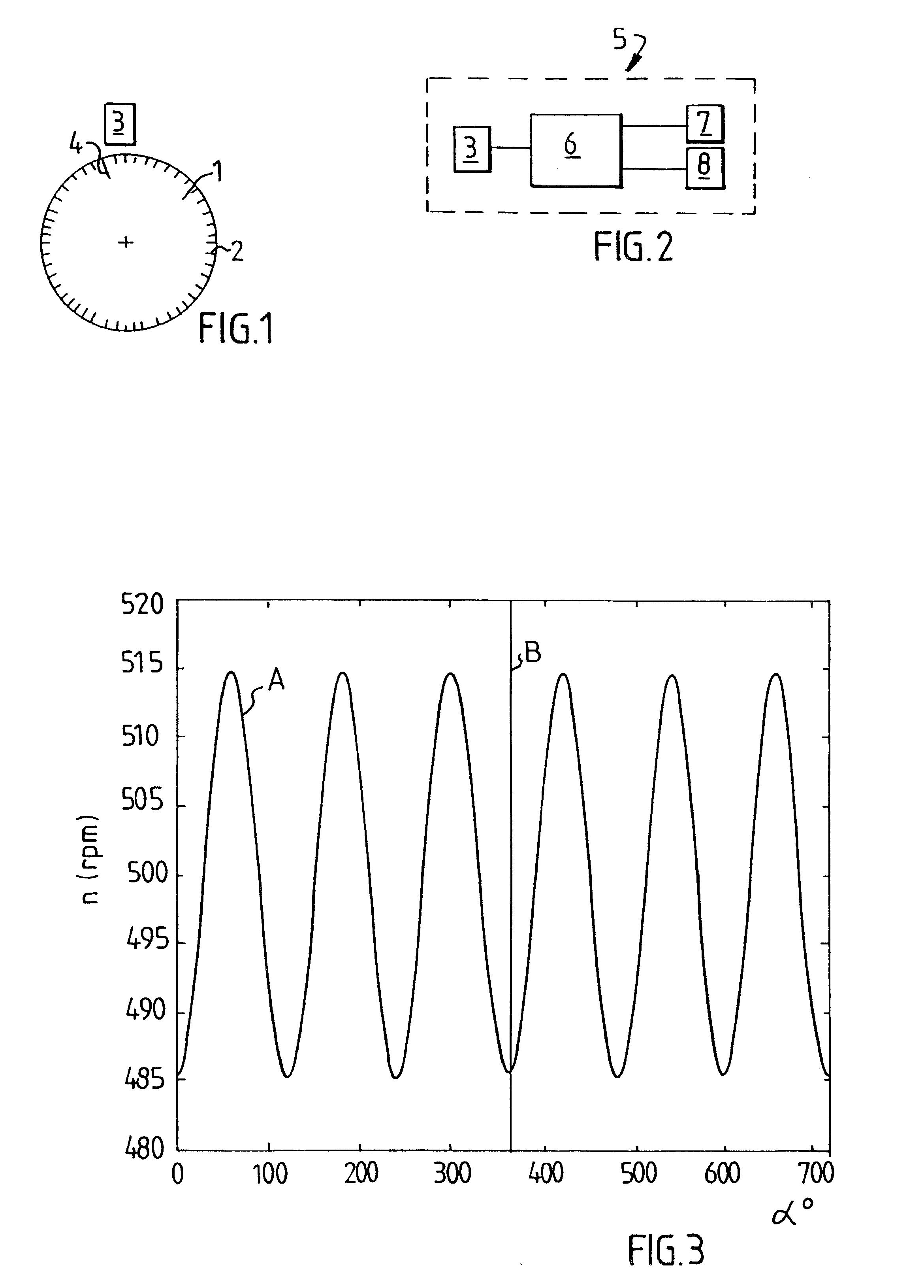
FIG. 1 shows how a flywheel 1 of an otherwise not shown engine with fuel injection is provided with a number of indications 2, for example in the form of teeth, which are distributed in the circumferential direction and can be read off by a rota...


PUM


Abstract

In a multiple cylinder four-stroke engine with fuel injection, an interference oscillation is generated briefly on the flywheel on starting by varied fuel supply to different cylinders. After oscillation analysis of the resultant oscillation of the flywheel, phase positions of the superimposed interference oscillation and of the resultant oscillation are compared. If predetermined phase positions of the oscillations appear, the engine is considered to be operating in the correct cycle position, but otherwise a control unit is initiated to correct its cycle position so that the correct cycle position of the engine is obtained.

Description

The present invention relates to on the one hand a method of determining where the cylinders of a multiple cylinder engine are operating during their operating cycle and for adjusting the cycle positions of the cylinders and on the other hand to an arrangement for the determining and adjusting.STATE OF THE ARTIn internal combustion engines of the four-stroke type, the camshaft rotates at half the crankshaft speed, as a result of which the rotary position of the camshaft at any moment clearly indicates where in its operating cycle, or in which cycle position, a given cylinder is located. By studying the rotary position of the camshaft, it is therefore possible to determine whether the current position of the piston in a cylinder is to be assigned to the first or the second crankshaft revolution in each operating cycle of the cylinder. By means of camshaft sensors, it is thus possible to provide, for example, an electronic control unit for a fuel injection system with reliable informa...

Claims


Application Information

Patent Timeline
Patent Type & Authority Patents(United States)
IPC IPC(8): F02D41/14F02D41/34F02N11/08F02D41/02F02D41/06F02D45/00
CPCF02D41/009F02D41/1408F02D2041/0092
Inventor PETTERSSON, MAGNUS
Owner SCANIA CV AB
Why Eureka
Try Eureka