
Methods and apparatus for improved vaporization of deposition material in a substrate processing system

a technology of deposition process and substrate, which is applied in the direction of combustion air/fuel air treatment, machines/engines, transportation and packaging, etc., can solve the problems of affecting the vaporization rate, affecting the vaporization effect of deposition material,

Inactive Publication Date: 2003-07-22
APPLIED MATERIALS INC
View PDF19 Cites 63 Cited by
  • Summary
  • Abstract
  • Description
  • Claims
  • Application Information

AI Technical Summary

Benefits of technology

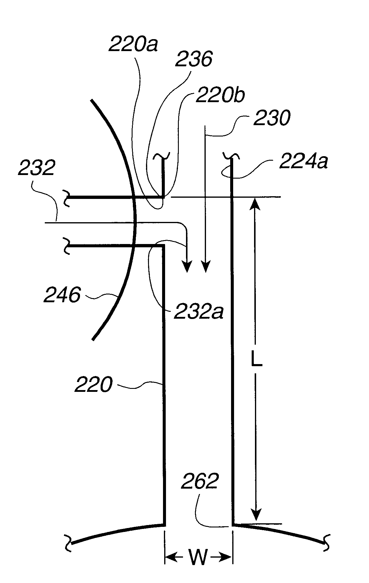
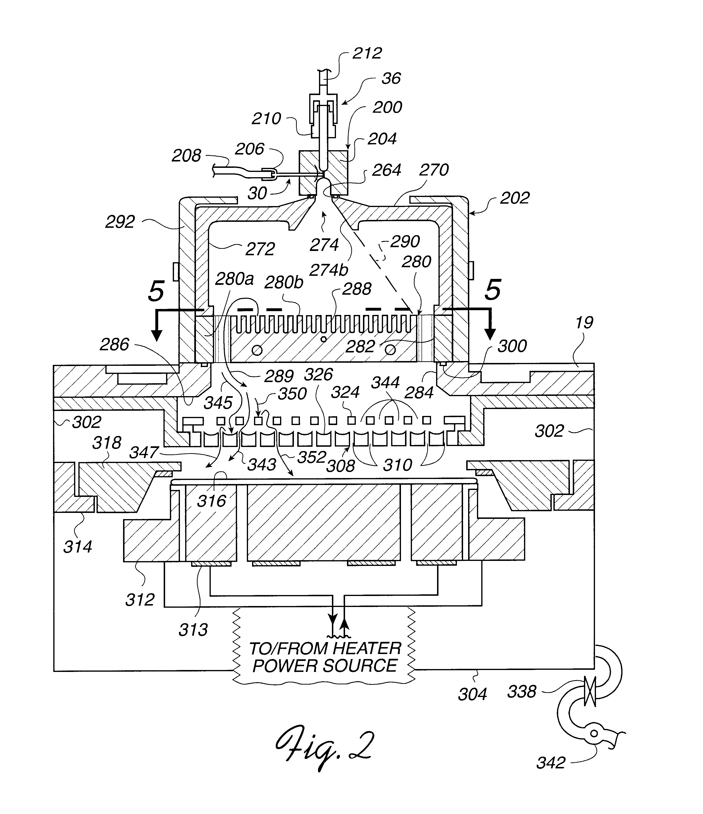
In one aspect of the present inventions, improved methods and apparatus for vaporization of deposition material in a deposition process system are provided. For example, in the illustrated embodiment, a vaporizer includes a body defining a cavity having an outlet and a recessed inlet wherein the cavity outlet is larger than the recessed cavity inlet. The vaporizer body further defines a first passageway coupled to the inlet and adapted to carry a mixed flow of carrier gas and a liquid precursor to the cavity inlet. The passageway has a relatively short length and small width to form small particles of the liquid precursor and to inhibit recombination of the liquid precursor to larger droplets. The cavity is shaped to permit the mixed flow of carrier gas and liquid precursor to expand as it flows from the cavity inlet to the cavity outlet. As a consequence, the liquid precursor is dispersed by the carrier gas expanding through the cavity.
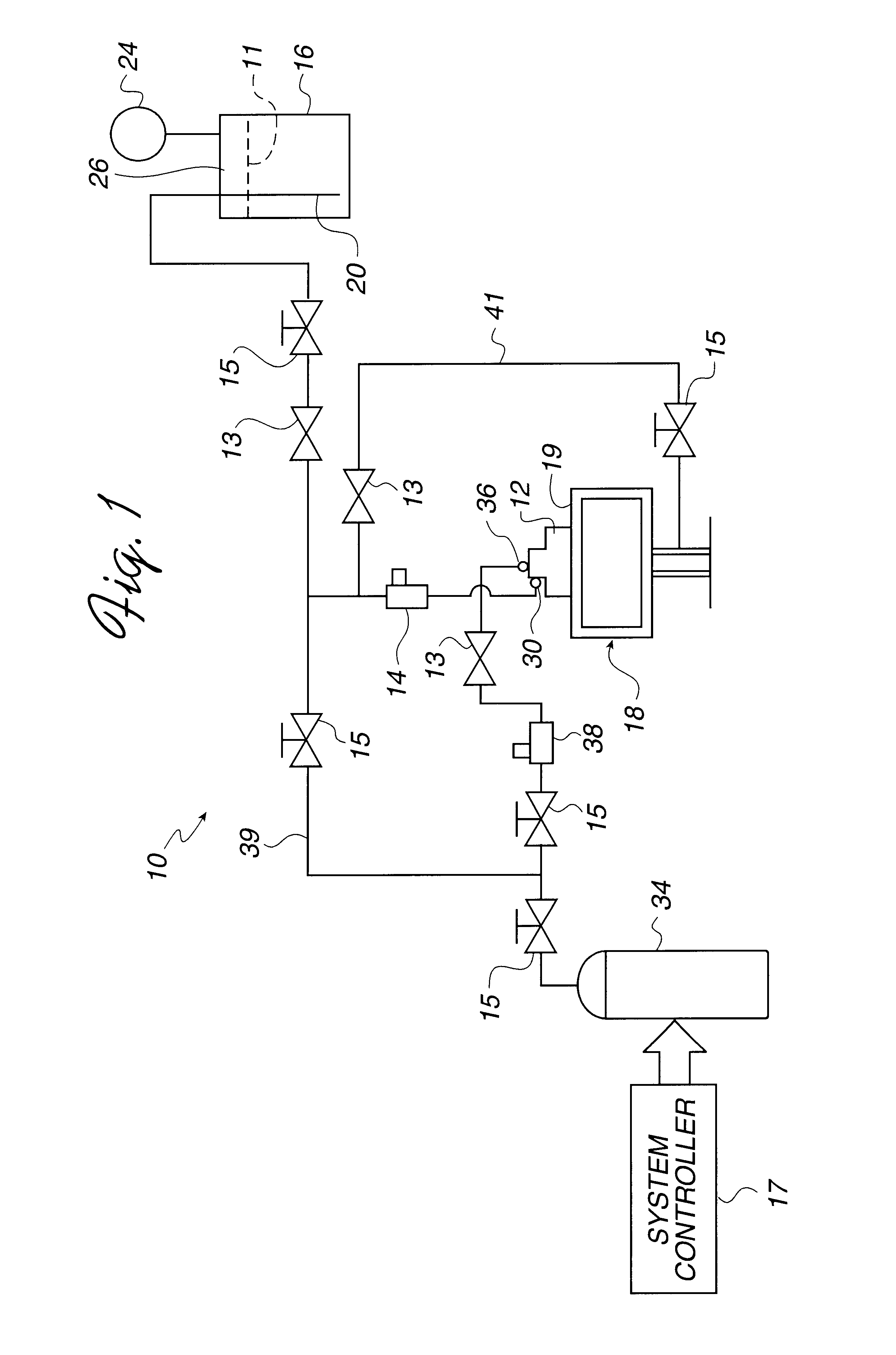
The novel deposition system described above may provide for an improved CVD operation by more completely and uniformly dispersing and vaporizing a precursor material in a chamber. Additionally, various features of the deposition system may include a reduction in the likelihood of clogging or excessive and undesirable plating that potentially creates particles in the chamber and / or premature failure or excessive maintenance of system components.

Problems solved by technology

One problem associated with using Cupraselect.RTM. for CVD can occur in the delivery of the material from its liquid storage ampoule to the process chamber in which the CVD occurs.
Unfortunately, raising the temperature too high can cause breakdown of the precursor and subsequent plating (deposition) in transfer lines between the ampoule and process chamber.
Unfortunately, these devices can clog after vaporizing only about 50-1500 g of Cupraselect.RTM.. Such clogs can alter the deposition rate.
Under these conditions, undesirable plating or deposition is also likely to occur at various locations.
Plating can change the dimensions of these system components which can degrade performance of the chamber and the resultant deposition layer.
Additionally, unwanted plating may flake off during the deposition process which can render a processed wafer faulty or unusable.

Method used


Image

  • Methods and apparatus for improved vaporization of deposition material in a substrate processing system
  • Methods and apparatus for improved vaporization of deposition material in a substrate processing system
  • Methods and apparatus for improved vaporization of deposition material in a substrate processing system

Examples


Embodiment Construction

In one aspect of the present inventions, improved methods and apparatus for vaporization of deposition material in a deposition process system are provided. For example, in the illustrated embodiment, a vaporizer includes a body defining a cavity having an outlet and a recessed inlet wherein the cavity outlet is larger than the recessed cavity inlet. The vaporizer body further defines a first passageway coupled to the inlet and adapted to carry a mixed flow of carrier gas and a liquid precursor to the cavity inlet. The passageway has a relatively short length and small width to form small particles of the liquid precursor and to inhibit recombination of the liquid precursor to larger droplets. The cavity is shaped to permit the mixed flow of carrier gas and liquid precursor to expand as it flows from the cavity inlet to the cavity outlet. As a consequence, the liquid precursor is dispersed by the carrier gas expanding through the cavity.

In the example of the illustrated embodiment, ...


PUM

PropertyMeasurementUnit
Lengthaaaaaaaaaa
Lengthaaaaaaaaaa
Volumeaaaaaaaaaa

Abstract

A deposition system for performing chemical vapor deposition comprising deposition chamber and a vaporizer coupled to said chamber. In one aspect, the vaporizer has a relatively short mixing passageway to mix a carrier gas with a liquid precursor to produce a fine aerosol-like dispersion of liquid precursor which is vaporized by a hot plate.

Description

BACKGROUND OF THE DISCLOSURE1. Field of the InventionThe present inventions are directed toward the field of manufacturing integrated circuits. The inventions are more particularly directed toward improved methods and apparatus for vaporization of deposition material in a deposition process system.2. Description of the Related ArtPresently, aluminum is widely employed in integrated circuits as an interconnect, such as plugs and vias. However, higher device densities, faster operating frequencies, and larger die sizes have created a need for a metal with lower resistivity than aluminum to be used in interconnect structures. The lower resistivity of copper makes it an attractive candidate for replacing aluminum. There are well established techniques for depositing copper, including electroplating, chemical vapor deposition ("CVD") and physical vapor deposition ("PVD"). A CVD process is desirable because it can often provide for a more conformally deposited layer. For example, chemical...

Claims


Application Information

Patent Timeline
IPC IPC(8): B01F3/04C23C16/448H01L21/205C23C16/455H01L21/285H01L21/31
CPCB01F3/04049C23C16/4486B01F23/2132C23C16/45565
Inventor SCHMITT, JOHN VINCENTLI, SHIH-HUNGMARCADAL, CHRISTOPHECHANG, ANZHONGCHEN, LING
Owner APPLIED MATERIALS INC
Learn More