
Exceptions and interrupts with dynamic priority and vector routing

Inactive Publication Date: 2003-07-29
IBM CORP
View PDF12 Cites 13 Cited by
  • Summary
  • Abstract
  • Description
  • Claims
  • Application Information

AI Technical Summary

Benefits of technology

It is yet another object of the present invention to provide such a method that further allows a user to define which interrupts are to be considered critical.

Problems solved by technology

It is not always possible, however, to take full advantage of these speed gains due to other problems, such as the frequency of I / O operations.
Two components of I / O operations that slow a system down are the interrupt processing delays (latencies) and the relatively slow operation of the I / O busses.
It requires both non-volatile and volatile memory attached to boot the processor and run the functional code, and is thus a relatively expensive approach.
This approach does not fully address interrupt latency issues since it only allows the system to route the interrupt to a processor running the lowest priority task.
In a truly embedded environment, both the relatively fixed interrupt locations and the fixed definition of which interrupts are critical and non-critical are very limiting.
In an embedded application, some interrupts are more time-critical than others.
The 40x method of a predefined definition of which interrupts are considered critical does not allow the user the flexibility to tune the processor to the user's application.
Provision of such a data storage processor is relatively expensive, as with the above-noted approach.
Also, providing a processor as part of the main CPU complex is more limiting, since it cannot be scaled for multi-bus systems, and still has the problems attributed to the I / O latency issues.
Designs such as that disclosed in U.S. Pat. No. 5,557,764 require "injecting" interrupts from on-chip RAM, but still do not allow an ISR to selectably reside either on- or off-chip.

Method used


Image

  • Exceptions and interrupts with dynamic priority and vector routing
  • Exceptions and interrupts with dynamic priority and vector routing
  • Exceptions and interrupts with dynamic priority and vector routing

Examples


Embodiment Construction

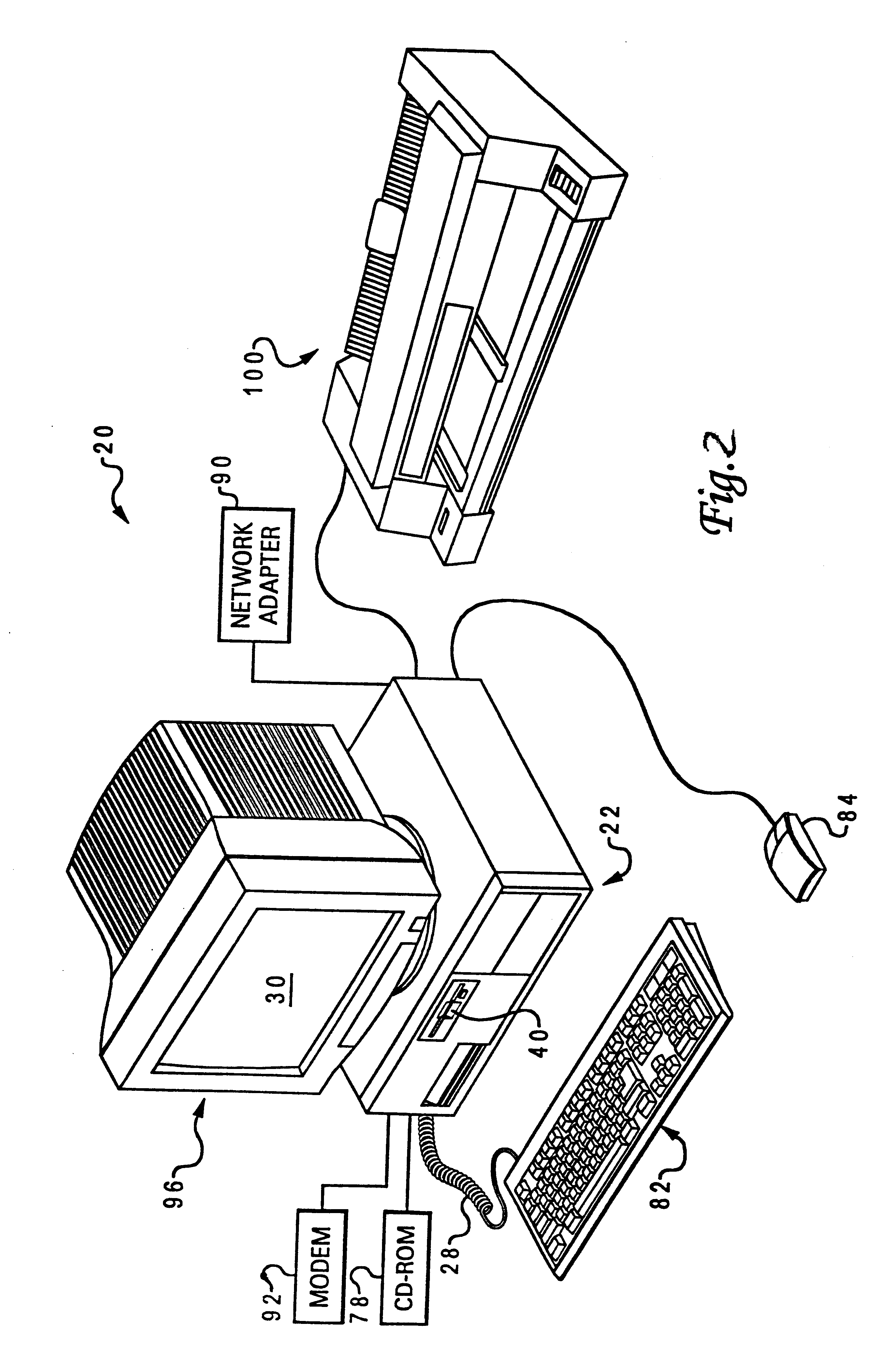
With reference to FIG. 2, a data processing system 20 is shown in which the present invention can be practiced. The data processing system 20 includes at least one processor 22, a keyboard 82, and a display 96. Keyboard 82 is coupled to processor 22 by a cable 28. Display 96 includes display screen 30, which may be implemented using a cathode ray tube (CRT), a liquid crystal display (LCD), an electrode luminescent panel or the like. The data processing system 20 also includes pointing device 84, which may be implemented using a track ball, a joy stick, touch sensitive tablet or screen, track path, or as illustrated a mouse. The pointing device 84 may be used to move a pointer or cursor on display screen 30. Processor 22 may also be coupled to one or more peripheral devices such a modem 92, CD-ROM 78, network adapter 90, and floppy disk drive 40, each of which may be internal or external to the enclosure or processor 22. An output device such as a printer 100 may also be coupled with...


PUM


Abstract

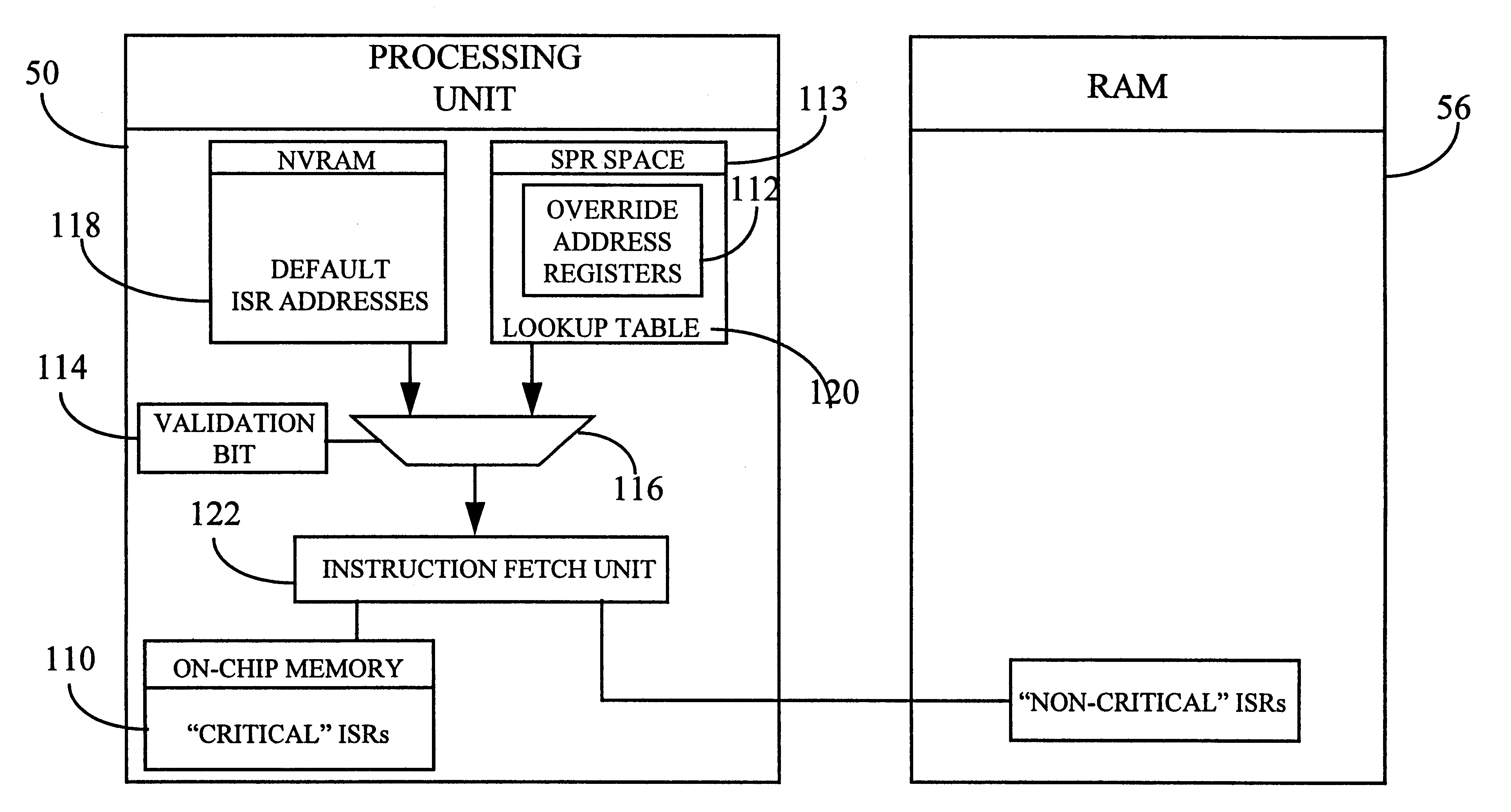
A method of handling an interrupt request in a computer system by programmably setting an override address associated with a specific interrupt service routine, and servicing an interrupt request based on the override address, which is different from a power-on default address associated with the same interrupt service routine. The method may determine whether the interrupt service routine is critical and, if so, set the override address to a physical location in the on-chip memory of the processing unit, instead of in the off-chip memory (RAM). Override address registers are accessed via the special purpose registers of the processing unit. A validation bit may be turned on in response to the setting of the override address, with both the default address and the override address being provided as separate inputs to a multiplexing device controlled by the validation bit. The override address is forwarded from the multiplexing device to an instruction fetch unit whenever the validation bit has been set. The result is decreased latency associated with interrupt handling, and increased flexibility in user definition of critical versus non-critical interrupts.

Description

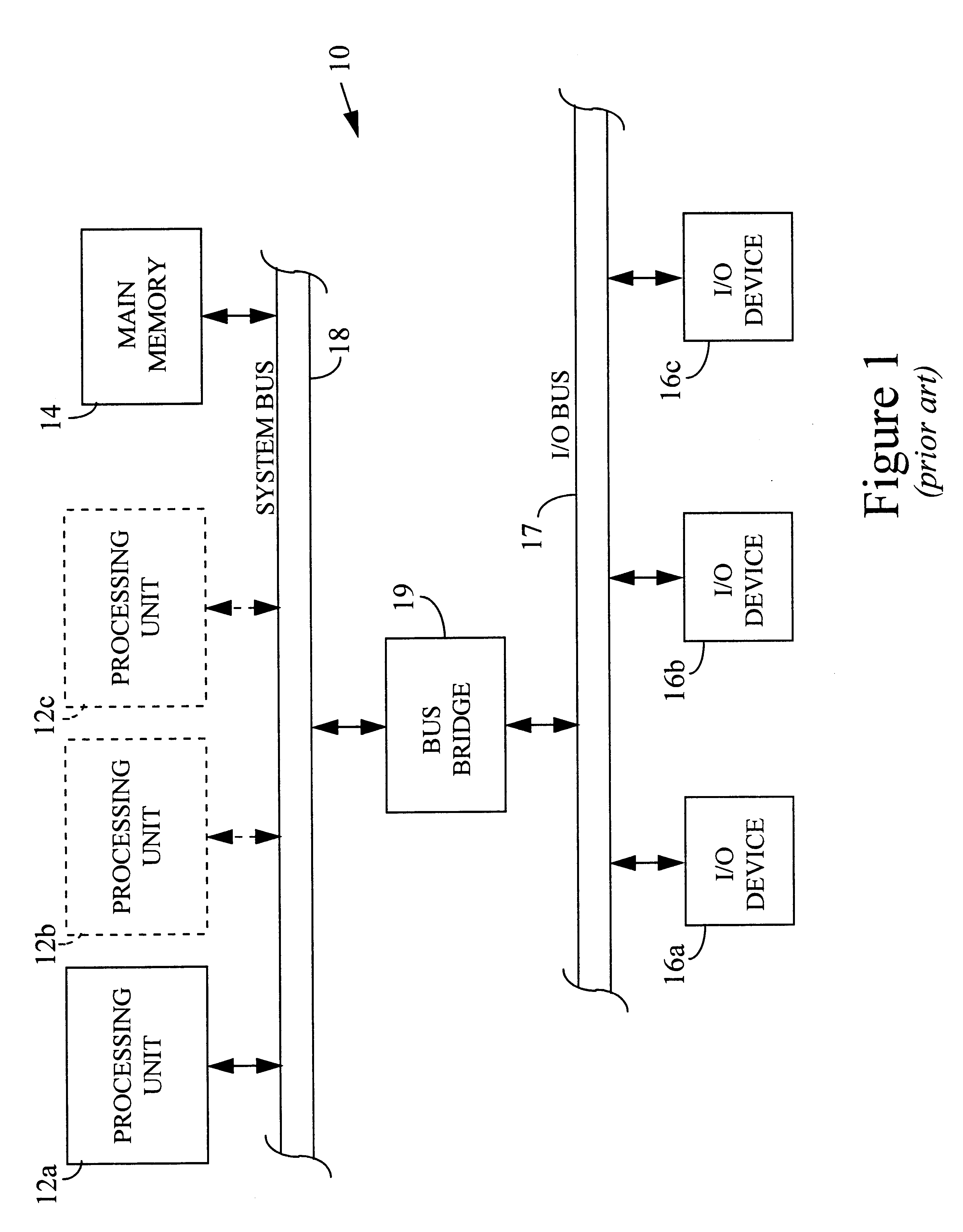
1. Field of the InventionThe present invention generally relates to computer systems, and more particularly to a method and apparatus for reducing latencies associated with interrupt / exception handling, and allowing increased flexibility in the provision of interrupt service routines.2. Description of the Related ArtA conventional computer system 10 is shown in FIG. 1, and includes one or more central processing units (CPUs) 12a, 12b and 12c, a main memory unit 14 (such as random access memory or RAM) that is used by the processing units to carry out program instructions. Computer system 10 also includes one or more input / output (I / O) units 16a, 16b, and 16c, such as a display monitor, keyboard, pointing device (mouse), and a permanent memory device (such as a hard disk or floppy diskette) for storing the computer's operating system and user programs. Computer system 10 may have many additional components which are not shown, such as serial, parallel and universal bus ports for conn...

Claims


Application Information

Patent Timeline
IPC IPC(8): G06F9/48G06F9/46G06F13/24
CPCG06F9/4812G06F13/24
Inventor BROBERG, III, ROBERT N.BYRN, JONATHAN W.MCBRIDE, CHAD B.MCCLANNAHAN, GARY P.
Owner IBM CORP
Learn More