Twist drill

a twist drill and drill bit technology, applied in the field of twist drills, can solve the problems of large range of required drill lengths and drill diameters, large cost of twist drills, and large drilling diameters,

Inactive Publication Date: 2003-08-05
HILTI AG
View PDF4 Cites 25 Cited by
  • Summary
  • Abstract
  • Description
  • Claims
  • Application Information

AI Technical Summary

Benefits of technology

Another object of the present invention is to provide a twist drill which can be produced in a simple manner in a wide range of drill lengths and drill diameters.
Advantageously, the spiral is formed with a steep start angle of more than 45.degree. which permits to transmit to the shaft sufficiently large axial impact components. Further, advantageously, instead of a conventional two-start spiral, a three-start spiral is formed which insures high efficiency in removing the drilled-off material and good guidance of the drill in the drilled bore.
Advantageously, the outer cross-sectional profile of the spiral has a trigonal symmetry with respect to the drill axis, which provides for a high flexural section modulus of the shaft in all directions and for uniform guidance of the twist drill along the wall of the drilled bore.
Advantageously, a spiral groove of the outer cross-sectional profile of the spiral forms a concave curve which increases the cross-section of the spiral groove and, thereby, the delivery volume.
Advantageously, the circle inscribed in the outer cross-sectional profile has a radius which amounts to from 0.4 to 0.7 times of the spiral radius. This insures transmission of an adequate tortional torque at a sufficient cross-section of the spiral groove.
Advantageously, the hollow shaft is filled with hollowed, viscoelastic material, which provides for vibration damping of the twist drill. By filling the hollow shaft, which is formed of a vibration-free, to a most possible extent, material, with the viscoelastic material, an optimal damping or filtering, with respect to main modes excited in the shaft during drilling, is achieved. The used filling viscoelastic material has a high damping value in a range of operational temperatures in which the frequency range of main modes prevails.

Problems solved by technology

The manufacturing of twist drills, because of the large range of required drill lengths and drill diameters, is rather expensive.
Moreover, the twist drill, which is formed of a solid material, is relatively heavy.
Therefore, when such twist drills are used in construction, the large number of different twist drills, which is required, makes their carrying very difficult due to their large combined weight.

Method used


Image

  • Twist drill
  • Twist drill

Examples


Embodiment Construction

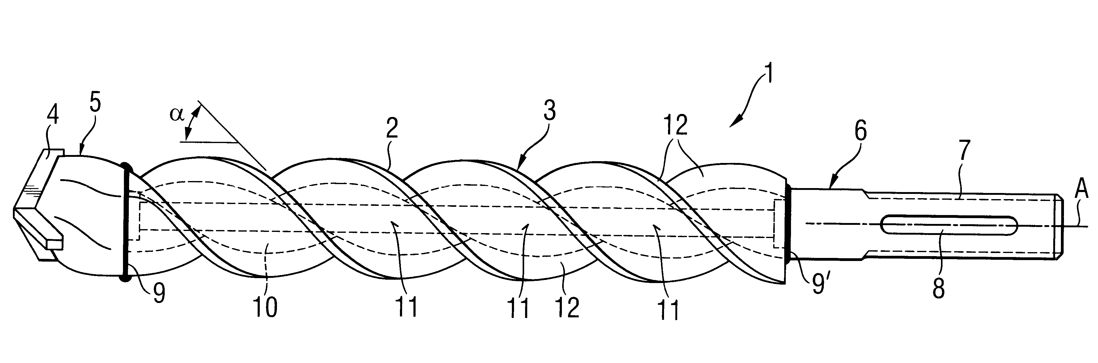
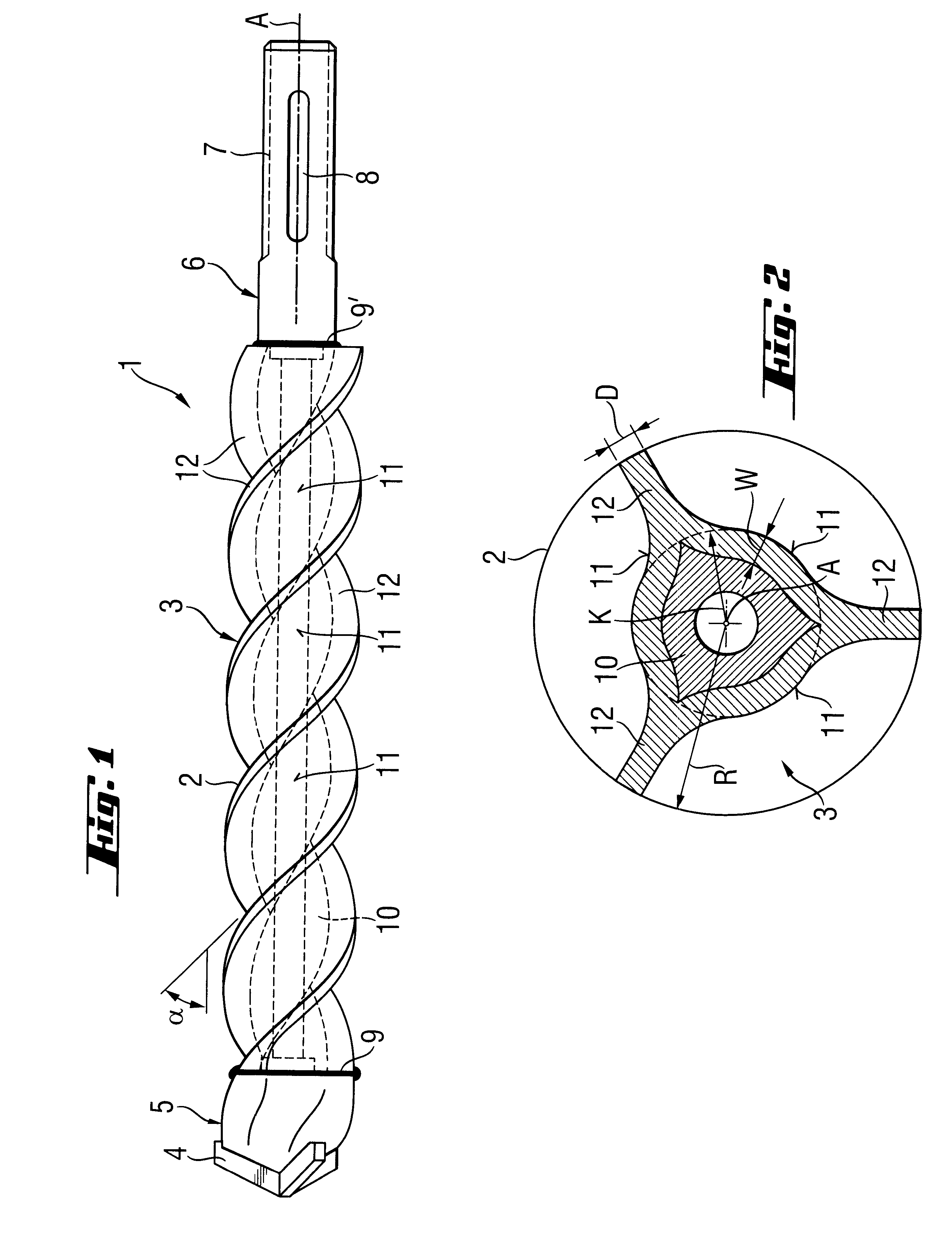
A twist drill 1 according to the present invention, which is shown in the drawings, includes a hollow shaft 3 which forms a spiral 2 and has an inner spiral-shaped surface, a drilling head 5 which is provided at one end of the shaft 3, and a shank 6 which is provided at another end of the shaft 3. The drilling head 5 is formed symmetrically with respect to its cutting bit 4 formed of a hard material. The shank 6 is provided with entraining grooves 7 and locking grooves 8 and is so formed that it appropriately engages in the shaft 3, formlockingly by interlocking of the materials of the shank 6 and the shaft, by circumferential connection seams 9 and 9'. The three-start spiral 2 is formed as a steep spiral and with a start angle .alpha. of 50.degree.. The hollow shaft 3 is filled with a viscoelastic, hollowed, as a result of being centrifuged, material 10.

As shown in FIG. 2, the outer cross-sectional profile of the spiral 2 has a trigonal symmetry with respect to the drill axis A. Th...


PUM

PropertyMeasurementUnit
start angleaaaaaaaaaa
hardaaaaaaaaaa

Abstract

A twist drill including a spiral-forming hollow shaft (3) having a spiral-shaped inner surface, and drilling head(5) and shank (6) connected with the shaft (3) at its opposite ends, respectively; and a method for forming such a twist drill.

Description

1. Field of the InventionThe present invention relates to a twist drill, which is subjected to torsional and impact loads, for abrasive removal of stone and stone-like materials such as concrete and brickwork.2. Description of the Prior ArtTwist drills of the type described above are used with hand-held power tools, automatic power tools, and robot-operated power tools, e.g., in construction.A twist drill includes a shaft forming, at least partially, a spiral, a drilling head formed of a hard material or provided with inserts formed of a hard material for removing stone material, and a shank provided at the shaft end opposite to the end at which the drilling head is secured. The shank is usually provided with entraining and locking grooves and is received in a power tool for joint rotation therewith and with a possibility of a limited axial movement relative thereto. Special shanks are used when particular functions such as introduction of cooling liquid or dust removal are contempl...

Claims


Application Information

Patent Timeline
Patent Type & Authority Patents(United States)
IPC IPC(8): B28D1/14B23B51/02B23P15/32B23B51/00B21H3/10E21B10/44
CPCB23B51/02B23P15/32B28D1/146E21B10/445B21H3/10B23B2226/75B23B2251/02Y10T408/9097B25D2217/0034B23B2251/241
Inventor SAITTA, ROBERT S.WELLS, TROY D.PUTZI, CHRISTIAN
Owner HILTI AG
Why Eureka
Try Eureka