Method of producing fuel hose and fuel hose obtained thereby

a technology of fuel hoses and hoses, which is applied in the direction of synthetic resin layered products, insulation conductors/cables, other domestic articles, etc., can solve the problems of insufficient thermoplastic resin outer layer and insufficient adhesive strength between tubular fluororesin inner layer and adhesive strength, and achieve superior initial adhesive strength, improved adhesive strength, and improved adhesion strength

Inactive Publication Date: 2003-08-05
SUMITOMO RIKO CO LTD
View PDF24 Cites 34 Cited by
  • Summary
  • Abstract
  • Description
  • Claims
  • Application Information

AI Technical Summary

Benefits of technology

The inventors of the present invention already have found that adhesive strength between the tubular fluororesin inner layer and the thermoplastic resin outer layer was improved by plasma-treating a surface of the tubular fluororesin inner layer so that superior initial adhesive strength can be obtained. This is because fluorine atoms and hydrogen atoms are set free from molecules of the fluororesin by the plasma treatment so as to produce carbon radicals, which react with the atmosphere so as to produce adhesive functional groups, the surface concentration of fluorine atoms decreases by defluorination, and the plasma-treated peripheral surface becomes uneven. As a result of further researches on the plasma-treated fuel hose, the inventors found that the surface concentration of fluorine atoms is still high on the peripheral surface of the tubular fluororesin inner layer and functional groups having fluorine atoms not involved in adhesion are widely distributed therein by conducting plasma treatment only so that adhesive strength between the tubular fluororesin inner layer and, the thermoplastic resin outer layer is insufficient. As a result of still further researches, the inventors found that the functional groups having fluorine atoms not involved in adhesion go inside the tubular fluororesin inner layer by conducting at least one of water treatment and silane coupling agent aqueous solution treatment on the plasma-treated peripheral surface so that the surface concentration of fluorine atoms decreases on the peripheral surface of the tubular fluororesin inner layer and the distribution of the functional groups having fluorine atoms not involved in adhesion decreases while adhesive functional groups (functional groups having oxygen atoms) such as an OH group widely distribute therein. As a result, the inventors found that adhesive strength between the tubular fluororesin inner layer and the thermoplastic resin outer layer is improved by conducting the at least one of water treatment and silane coupling agent aqueous solution treatment on the plasma-treated peripheral surface. As a result, a fuel hose superior in adhesive reliability can be obtained since deterioration in adhesive strength after heat aging and immersion into fuel can be restrained under severe conditions such as an inside of an engine compartment. Thus, the inventors have attained the present invention. Especially, in the case that silane coupling agent aqueous solution treatment is conducted on the plasma-treated peripheral surface, a silane coupling agent layer can be formed on a surface of the tubular fluororesin inner layer so that each adhesive strength between the tubular fluororesin inner layer and the silane coupling agent layer and between the silane coupling agent layer, and the thermoplastic resin outer layer is further improved, respectively.
In the fuel hose according to, the present invention, functional groups having oxygen atoms such as OH groups are distributed on the peripheral surface of the tubular fluororesin inner layer. Since the functional groups having oxygen atoms are involved in adhesion, the adhesion strength between the tubular fluororesin inner layer and the thermoplastic resin outer layer can be improved.

Problems solved by technology

As a result of further researches on the plasma-treated fuel hose, the inventors found that the surface concentration of fluorine atoms is still high on the peripheral surface of the tubular fluororesin inner layer and functional groups having fluorine atoms not involved in adhesion are widely distributed therein by conducting plasma treatment only so that adhesive strength between the tubular fluororesin inner layer and, the thermoplastic resin outer layer is insufficient.

Method used


Image

  • Method of producing fuel hose and fuel hose obtained thereby
  • Method of producing fuel hose and fuel hose obtained thereby
  • Method of producing fuel hose and fuel hose obtained thereby

Examples


example 2

A fuel hose was produced in the same manner as EXAMPLE 1 except that a 0.1% by weight acetic aqueous acid solution (pH=4.+-.0.2) was used, as shown in the following Table 1, instead of the pure water (pH=7) of EXAMPLE 1.

example 3

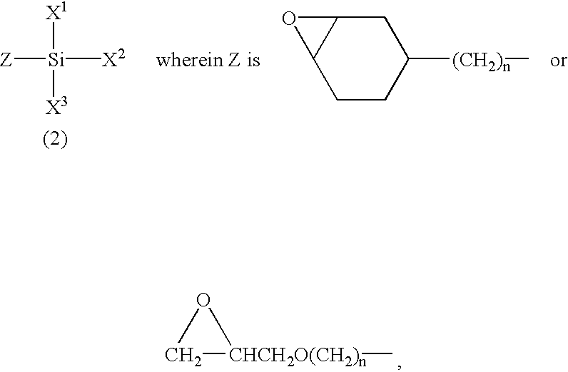
A fuel hose was produced in the same manner as EXAMPLE 1 except that an aqueous solution of 1% by weight silane coupling agent (A) in pure water (pH=7) was used, as shown in the following Table 2, instead of the pure water (pH=7) of EXAMPLE 1. In addition, the application amount (excluding aqueous solution) of the silane coupling agent was 3.times.10.sup.-7 g / cm.sup.2 based on a plasma-treated peripheral surface of the tubular fluororesin inner layer.

example 4

A fuel hose was produced in the same manner as EXAMPLE 3 except that the silane coupling agent (B) was used, as shown in the following Table 1, instead of the silane coupling agent (A) of EXAMPLE 3.


PUM

PropertyMeasurementUnit
pHaaaaaaaaaa
thicknessaaaaaaaaaa
thicknessaaaaaaaaaa

Abstract

A method of producing a fuel hose having superior adhesive reliability with superior initial adhesive strength between a tubular fluororesin inner layer and a thermoplastic resin outer layer and with restrained deterioration in adhesive strength after heat aging and immersion into fuel under severe conditions such as an inside of an engine compartment. The method includes plasma treatment on a peripheral surface of the tubular fluororesin inner layer, at least one treatment of water treatment and silane coupling agent treatment on the plasma treated surface and formation of the thermoplastic resin outer layer on the treated peripheral surface.

Description

The present invention relates to a method of producing a fuel hose for use in a fuel system of a motor vehicle or other equipment and a fuel hose obtained thereby.PRIOR ARTGenerally, fuel hoses used in fuel systems of cars and other equipment have multi-layer structures comprising various rubber and resin layers. Among such multi-layer fuel hoses, a two-layer fuel hose comprising a fluororesin inner layer and a thermoplastic resin outer layer laminated on a peripheral surface of the inner layer is in prevalent use. Since a fluororesin is superior not only in corrosion resistance and impermeability to chemicals, gasoline and the like but also in resistance to sour gasoline which is produced by oxidation of gasoline (sour gasoline resistance), a fluororesin is generally regarded as the optimal material for forming an inner layer of a fuel hose which is directly exposed to fuel. The thermoplastic resin outer resin layer is provided as a reinforcing member of the hose for imparting pres...

Claims


Application Information

Patent Timeline
Patent Type & Authority Patents(United States)
IPC IPC(8): B05D7/20B05D3/14B05D3/10B32B27/08C08J5/12F16L11/04B29C59/00B29C59/14
CPCB05D3/101B05D3/144B05D7/20C08J5/127F16L11/045B32B27/08B29C59/14B29K2027/12B29L2023/005Y10T428/1352C08J2327/12Y10T428/1379Y10T428/1383Y10T428/1393Y10T428/31663Y10T428/31746Y10T428/31743Y10T428/3154Y10T428/31667B32B2307/206B32B2307/202B32B2310/14B32B2597/00B32B1/08B32B27/34B32B2377/00
Inventor KATAYAMA, KAZUTAKAITO, HIROAKINISHIYAMA, TAKAHIROMURAKAMI, KOYOHAYAKAWA, TOMONORI
Owner SUMITOMO RIKO CO LTD
Why Eureka
Try Eureka