Modular gridless ion source

Inactive Publication Date: 2003-08-19
KAUFMAN & ROBINSON
View PDF4 Cites 48 Cited by
  • Summary
  • Abstract
  • Description
  • Claims
  • Application Information

AI Technical Summary

Benefits of technology

Still another specific object of the invention is to provide a gridless ion source with a detachable anode module in which the loss of working gas is minimized by a gas enclosure surrounding the anode in that module.
In accordance with one embodiment of the present invention, the ion-beam apparatus takes the form of an end-Hall ion source in which the detachable anode module incorporates the outer pole piece and includes an enclosure around the anode that both minimizes the loss of working gas and confines sputter contamination to the interior

Problems solved by technology

The need for maintenance can result from the limited lifetime of some parts, usually the cathode and the reflector.
As is known to those skilled in the art, the proper use of shadow shielding can reduce the rate at which sputtered coatings are deposited on ins

Method used


Image

  • Modular gridless ion source
  • Modular gridless ion source
  • Modular gridless ion source

Examples


Embodiment Construction

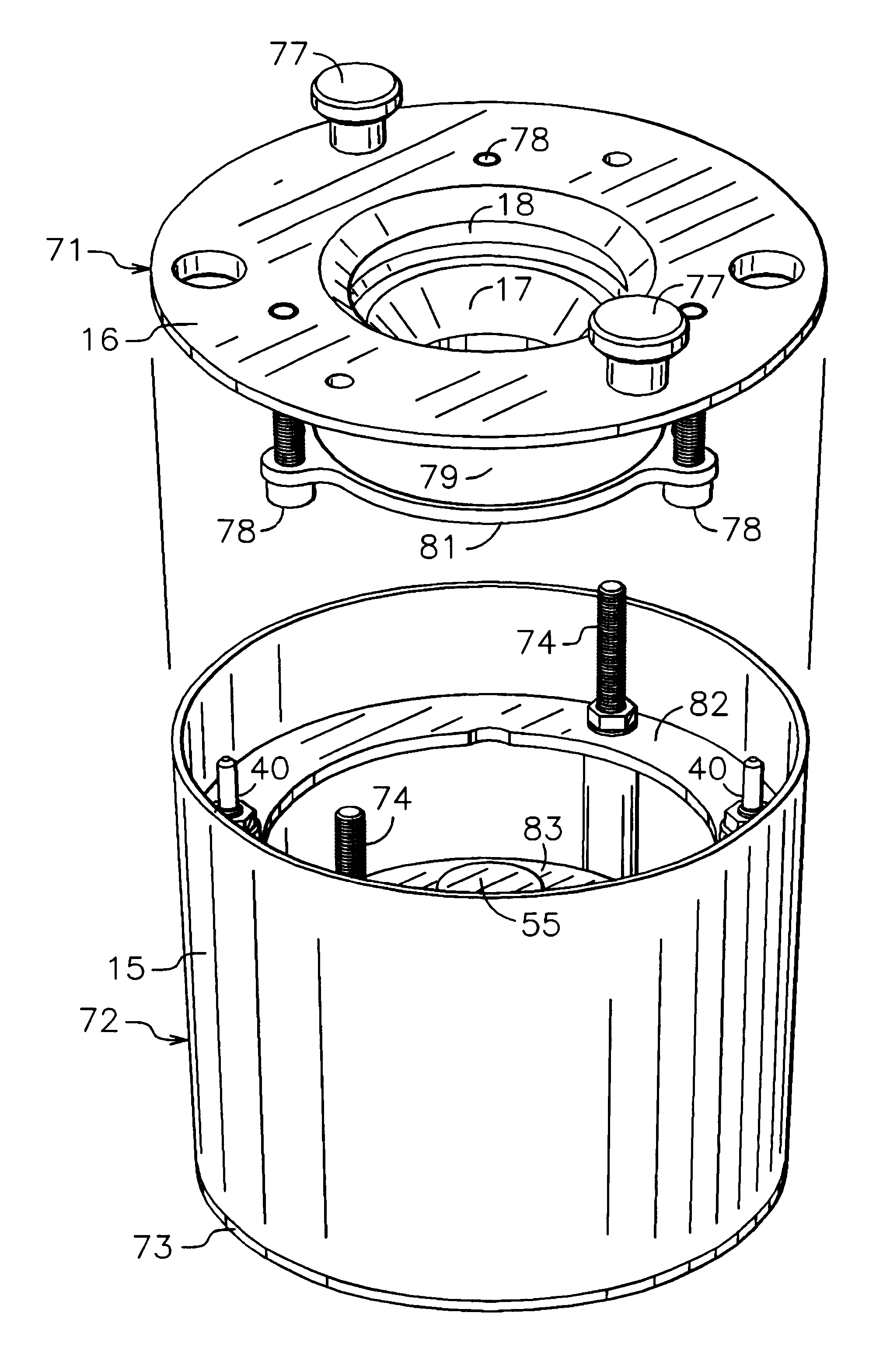
Referring to FIG. 5, there is shown a gridless ion source 70 of the end-Hall type that is an embodiment of the present invention. Ion source 70 is also generally of the type described in U.S. Pat. No. 4,862,032--Kaufman, et al., although it additionally incorporates a detachable anode module that facilitates rapid and economical maintenance.

Ion source 70 includes cathode assembly 13, detachable anode module 71, and magnetic-circuit module 72. Cathode assembly 13 includes cathode supports 23, cathode 24, and cathode retaining nuts 25. The components shown in FIG. 5 for the magnetic-circuit module include outer shell 15 and back plate 73, both of which are also parts of the magnetic circuit. Also parts of the magnetic-circuit module are threaded retainer rods 74.

Retaining nuts 76 are used to clamp anode module 71 to magnetic-circuit module 72. Outer pole piece 16 is part of the anode module and also part of the magnetic circuit. Because outer shell 15 remains with the magnetic-circuit...


PUM


Abstract

In accordance with one embodiment of the present invention, the ion-beam apparatus takes the form of an end-Hall ion source in which the detachable anode module incorporates the outer pole piece and includes an enclosure around the anode that both minimizes the loss of working gas and confines sputter contamination to the interior of this enclosure. This detachable anode module is substantially smaller than the entire end-Hall ion source, weighs substantially less, and can be duplicated for significantly less cost than the duplication of the entire ion source. In general, the components of the magnetic circuit determine the overall size, weight, and much of the cost of a gridless ion source. The reduced size, weight, and cost of the detachable anode module compared to the entire ion source is due to most of the magnetic circuit being excluded from the detachable module.

Description

This invention relates generally to ion and plasma sources, and more particularly it pertains to gridless or Hall-current ion sources.Industrial ion sources are used for etching, deposition and property modification, as described by Kaufman, et al., in the Characteristics, Capabilities, and Applications of Broad-Beam Sources, Commonwealth Scientific Corporation, Alexandria, Va. (1987).Both gridded and gridless ion sources are used in these industrial applications. The ions generated in gridded ion sources are accelerated electrostatically by the electric field between the grids. Only ions are present in the region between the grids and the magnitude of the ion current accelerated is limited by space-charge effects in this region. Gridded ion sources are described in an article by Kaufman, et al., in the AIAA Journal, Vol. 20 (1982), beginning on page 745. The particular sources described in this article use a direct-current discharge to generate ions. It is also possible to use elec...

Claims


Application Information

Patent Timeline
IPC IPC(8): F03H5/00F03H99/00
CPCH01J27/146
Inventor KAUFMAN, HAROLD R.
Owner KAUFMAN & ROBINSON
Why Eureka
Try Eureka