Shear wave generator

a generator and seismic wave technology, applied in seismology, instruments, water-covered areas, etc., can solve the problems of incurring a risk of sinking deeper into the sediment, incurring a risk of becoming stuck in the sea bed, and a lower transmission of the vibrator movement into the seismic wav

Inactive Publication Date: 2003-09-02
NORGES GEOTEKNISKE INST
View PDF7 Cites 41 Cited by
  • Summary
  • Abstract
  • Description
  • Claims
  • Application Information

AI Technical Summary

Benefits of technology

FIG. 1b illustrates a corresponding seismic signal transmitter having additional fins or wings on the coupling device for improved coupling of the seismic signal.

Problems solved by technology

a) To obtain sufficient coupling between the shear wave source and the consolidated sediments. This is Particularly related to soft sediments in the sea bed surface, with the sediments constituded by organic sediments, gyttja, mud, unconsolidated clay and other unconsolidated sediments having very low density compared to the underlying more consolidated sedimentary sea bed. This incurs an inferior transmission of the vibrators movements into seismic waves.
b) To release the shear wave source from the consolidated sediments. U.S. Pat. No. 4,705,137 will have a large surface which easily will stick firmly in the sea bed after vibration, requiring large forces to release from the sea bed. U.S. Pat. No. 5,128,900 will incur a risk of becoming stuck in the sea bed if it obtains a good fix, and may sink deeper into the sediments during vibration.
c) To achieve a uniform coupling to the sea bed during the entire vibration time. The two U.S. patent may sink deeper into the sediments during the seismic signal generation because they are given a wedge-shape penetrating into the sea bed and with vibration both being a means for attaching the signal source and also for generating the seismic signal. This may incur uncertainty during the interpretation of the seismic signal because one may not, to a sufficient degree, control the seismic characteristics of the source.

Method used


Image

  • Shear wave generator
  • Shear wave generator
  • Shear wave generator

Examples


Embodiment Construction

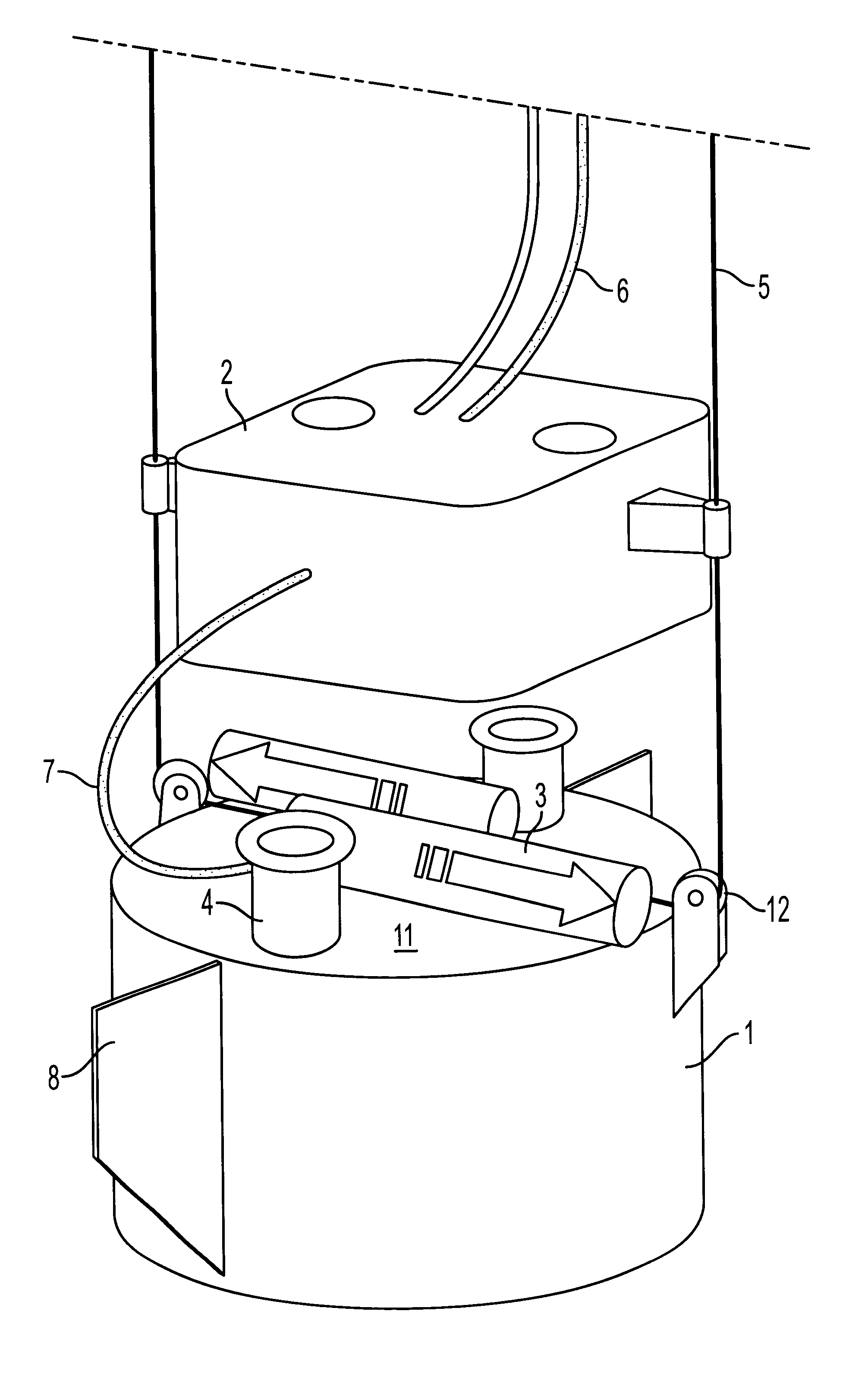
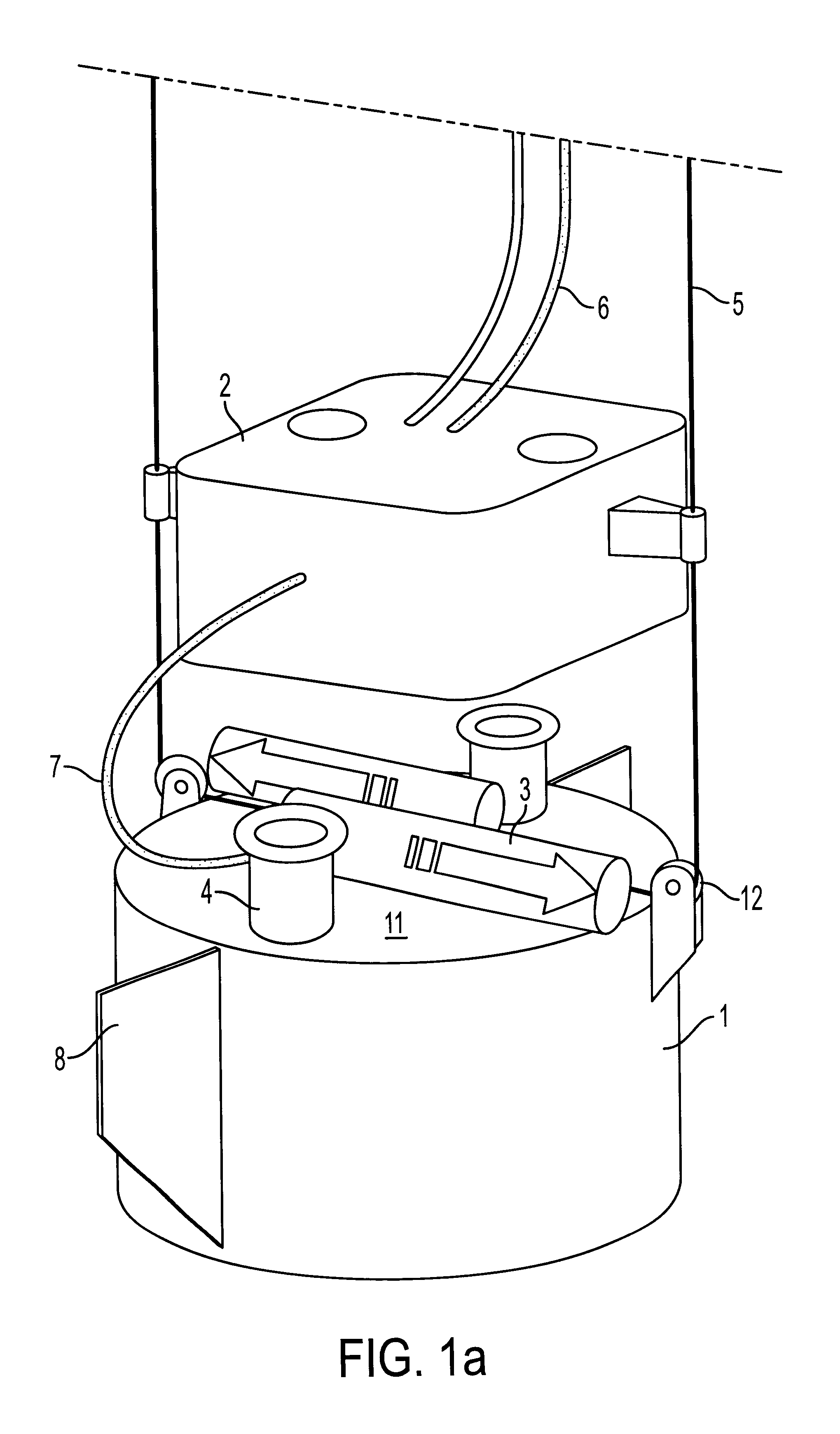
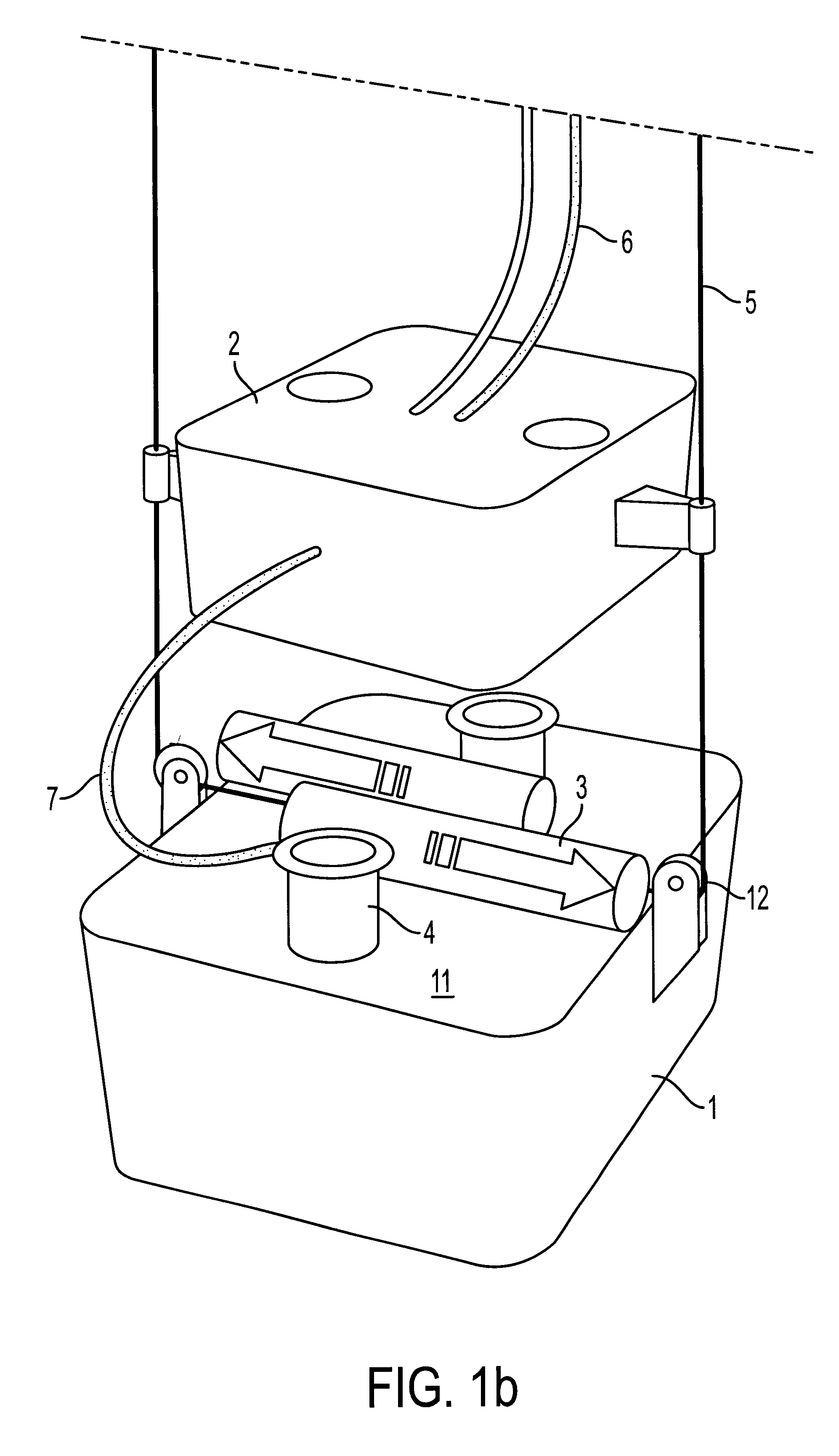
A preferred embodiment of the invention is illustrated in FIGS. 1a and 1b and comprises a seismic signal generator 3 arranged on a coupling device 1 arranged for suctioning into the sea bed sediment and unconsolidated masses. The coupling device 1 is constituted by a preferably metallic skirt 1 constituting the side surface of a cylinder or box being open in the one lower end arranged to penetrate downwards into sediments of the sea bed, and which in the opposite, upper end is closed by a closure 11 having a valve through arranged for being connected to a water pump- and power unit 2. One or more carrier wires 5 hold the skirt by extending eyelets or sheaves 12. The pump 2 may be arranged vertically mobile along the carrier wires 5, for guiding while connecting and disconnecting from the coupling device 1. The water pump / power unit 2 may alternatively be carried and operated by means of a semisubmersible vessel (ROV) 13. One of the advantages of such an arrangement is that the pump ...


PUM


Abstract

A seismic shear wave generator comprising a seismic wave source (3) arranged on a base plate (11) arranged for being placed at the seabed, and a coupling device (1) arranged for coupling the wave source (3) mechanically to the seabed in order for shear waves to be transmitted to the seabed. The novelty of the invention is as follows: a cylindrical skirt (1) closely arranged along the base plate's (11) circumference and extending down from the underside of the base plate (11), and open downwards, and a pump device (2) arranged for pumping water respectably out of, and into, the skirt (1) and form vacuum or overpressure, respectively, in a closed cavity formed by the skirt (1) and the base plate (11) and the seabed (1) is lowered onto the seabed. By means of the device mentioned above the shear wave generator may be suctioned fixed to the sea bed and thus transfer shear waves via the skirt (1) to the seabed.

Description

This application relates to a seismic sea bed source arranged for generating shear waves.More particularly it relates to a device for coupling a shear wave generator in a releasable way to a sedimentary sea bed.KNOWN ART IN THE FIELDU.S. Pat. No. 4,705,137 "Marine Shear Vibrator" describes a subsea vibrator apparatus for generating a shear wave into the consolidated sea bed, with a house, a horizontally arranged mass attached to the house for movement along an axis being mainly parallel to the earth's surface, and hydraulic apparatus for oscillating the mass along the axis. In essence the entire vibrator house comprises a sidewall and a bottom. The sidewalls and the bottom form a tapered surface with an angular surface of the tapered surface transversal to the mass'movement, so that the mass oscillates the subsea vibrator against the consolidated bottom, where the vibrator will sink and settle into the sea bed. However, the vibrator will maintain contact with the bottom even though ...

Claims


Application Information

Patent Timeline
Patent Type & Authority Patents(United States)
IPC IPC(8): G01V1/02G01V1/053G01V1/38
CPCG01V1/053G01V1/3808Y10S181/401
Inventor SPARREVIK, PERWESTERDAHL, HARALDMADSHUS, CHRISTIAN
Owner NORGES GEOTEKNISKE INST
Why Eureka
Try Eureka