Foam composite

a foam composite and foam technology, applied in the field of foam composites, can solve the problems of poor cell size control, low physical strength, and certain deficiencies, and achieve the effects of reducing the viscosity of the pre-polymer coating, reducing the viscosity, and similar viscosity/temperature curves

Inactive Publication Date: 2003-09-09
HYDROPHILIX +1
View PDF4 Cites 96 Cited by
  • Summary
  • Abstract
  • Description
  • Claims
  • Application Information

AI Technical Summary

Benefits of technology

In another embodiment of the invention the composite foams are provided by contacting the hydrophobic polyurethane foam with a liquid phase of a hydrophilic polyurethane prepolymer at temperatures sufficient to lower the viscosity and thereby control the coating weight of the hydrophilic prepolymer.
Referring now to FIG. 28, another embodiment of the invention is shown in which the foam composite 10 is utilized as a respirator for use in low temperature applications. The hydrophilic foam 14 in this embodiment contains a phase change material that melts and freezes at just below the temperature of the human body (98.6.degree. F / 37.degree. C.). The latent heat of fusion of the phase change material is used as a reservoir for storing the heat of exhaled air and subsequently releasing that heat to increase the temperature of inhaled air. Thus, in a respirator having two separate chambers and through which a person inhales through one chamber and exhales through the other, cold air enters the inhale side and is heated by the freezing phase change material. Air at body temperature is exhaled through the other chamber and melts the phase change material. This continues until the inhaled air freezes all of the phase change material. At that time, a valve is turned that reverses the inhale side to the exhale side and visa versa. The net effect is that the heat energy in the exhaled air is trapped and subsequently used to heat incoming air. The net effect is the breathed air temperature is tempered thus avoiding the body heat lost in very cold weather.

Problems solved by technology

While this hydrophilic nature gives hydrophlic polyurethane its unique applications, it also leads to certain deficiencies.
Among these are low physical strength, poor cell size control, relatively high densities causing a relatively high cost per unit volume, and the fact that foam swells considerably upon absorption.
Therefore, although the ability to incorporate certain active ingredients into the hydrophilic polyurethane foams is presently known in the art, this incorporation introduces many adverse characteristics into the foam, limiting the commercial use of hydrophilic polyurethane foams in engineering devices that utilize this technology.

Method used


Image

  • Foam composite
  • Foam composite
  • Foam composite

Examples


example 1

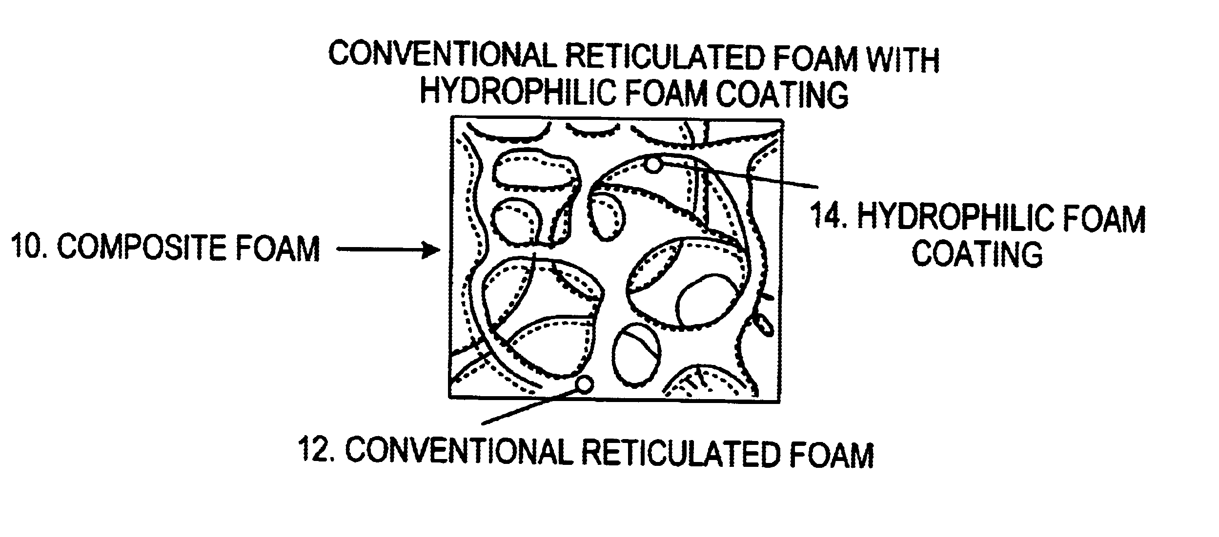
This example illustrates the preparation of foam composites by coating hydrophobic polyurethane scaffolds with an emulsion of polyurethane prepolymer.

Three (3) pieces of conventional hydrophobic reticulated foam having a pore size of 20 ppi such as Crest Foam, Grade S-20 were cut to 30.5 cm by 30.5 cm by 0.8 cm. Each weighed 16 grams. An emulsion was made using a mechanical mixer of a 0.1% Pluronic L62 (BASF Corp.) in water at ambient temperature and Rynel.RTM. (Grade B-1) hydrophilic polyurethane prepolymer (Rynel Ltd., Inc.). The emulsion was prepared by using 1 part prepolymer to 1.5 parts 0.1% Pluronic L62 solution. Three different amounts of the emulsion were immediately poured onto the three pieces of foam as shown in Table 5. In each case the entire emulsion was uniformly distributed onto the reticulated foam using a rolling pin. After curing, the entire amount of the prepolymer in the emulsion was found to form the coating of hydrophilic foam in the foam composite. The foam ...

example 2

This example illustrates the preparation of foam composites by coating reticulated hydrophobic polyurethane scaffolds with a solution of polyurethane prepolymer. A solution of the prepolymer was dissolved in a solvent such as acetone. The weight of the coating was controlled by varying the viscosity of the solution.

Three solutions of 10%, 20% and 30% of Rynel.RTM. prepolymer in acetone were prepared at ambient temperature. Samples of Crest.RTM. reticulated polyurethane foam as described in Example 1 above were dipped into the Rynel.RTM. prepolymer solutions. They were immediately removed and allowed to drain. They were then hung in a fume hood and the acetone was allowed to evaporate as evidenced by an absence of the acetone odor. The foam samples were then immersed in water at 25.degree. C. for about 10 minutes to cure. The samples were then dried and reweighed. They were subsequently placed in water at 25.degree. C. for 1 hour, patted dry to remove surface water and then re-weighe...

example 3

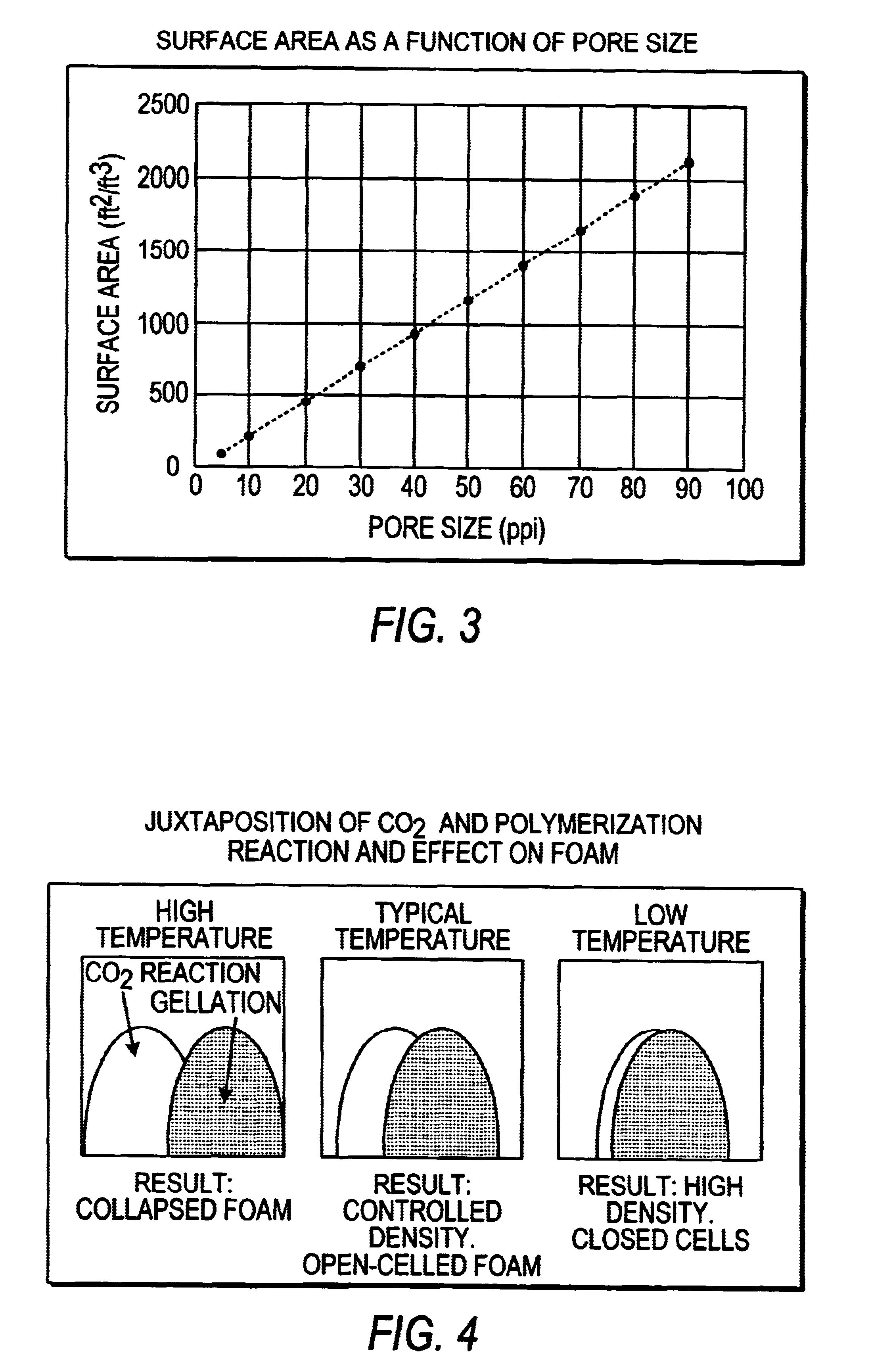
This example illustrates the preparation of foam composites by coating hydrophobic reticulated polyurethane scaffolds with undiluted polyurethane prepolymers having different viscosities. Prepolymers at three different temperatures were applied directly to Crest Foam.RTM. hydrophobic scaffolds as described below. The viscosity of commercial prepolymers was about 15,000 cps. at 25.degree. C. By heating the prepolymers their viscosity was lowered significantly. Three different foam composites having three different levels of open cell hydrophilic polyurethane coating were obtained.

Three (3) samples of the Rynel.RTM. prepolymer as described above were heated to 30.degree., 35.degree. and 40.degree. C. Three (3) samples of Crest.RTM. foam as described in Example 1 were each dipped into a prepolymer dip tank and then squeezed between rubber rollers. The samples were immediately immersed in water at 25.degree. C. to cure for about 30 minutes. The samples were dried and re-weighed. They we...


PUM

PropertyMeasurementUnit
thickaaaaaaaaaa
tensile strengthaaaaaaaaaa
temperatureaaaaaaaaaa

Abstract

A foam composite made up of a scaffold of a substantially hydrophobic foam material having plurality of surfaces defining a plurality of pores, and a coating of a substantially hydrophilic foam material disposed upon the surfaces of the hydrophobic foam. The resulting foam composite exhibits structural characteristics of the hydrophobic foam and absorbency characteristics of the hydrophilic foam.

Description

The present invention relates to the field of polymer chemistry and, in particular, to the field of foam composites having properties of both conventional hydrophobic and hydrophilic polyurethane foams.Conventional polyurethanes have taken a prominent position in the world as an inexpensive material for use in such diverse applications as foam insulation, adhesives, structural foams, shoe sole and others. The properties of conventional polyurethanes that make these uses possible are its physical strength, low cost, ability to make very low density foam, chemical resistance, and thermal stability.One of the variations of the product family is the manufacture of what are called reticulated foams. These foams are constructed such that the "windows" that separate the individual cells making up the foam structure are open and the material in the windows collapse into the "struts and beams". Thus when fully cured and viewed in a microscope, all one sees is a matrix of "tinker-toy-like" ro...

Claims


Application Information

Patent Timeline
Patent Type & Authority Patents(United States)
IPC IPC(8): B32B3/06B32B3/26B32B5/18C08J9/42
CPCB32B5/18C08J9/0009C08J9/365C08J9/405C08J9/42C08J2205/05C08J2375/04C08J2475/00Y10T428/249953Y10T428/249958Y10T428/249986Y10T428/24996Y10T428/249981Y10T428/249979Y10T428/249955Y10T428/249978Y10T428/249991Y10T428/249954
Inventor THOMSON, TIMOTHY
Owner HYDROPHILIX
Why Eureka
Try Eureka