Heat pump system of combination of ammonia cycle carbon dioxide cycle

a technology of ammonia cycle and heat pump system, which is applied in the direction of cooling fluid circulation, domestic cooling apparatus, lighting and heating apparatus, etc., can solve the problems of difficult to ensure safe and economical use of ammonia, hfc emission into the atmosphere has become strongly limited,

Inactive Publication Date: 2003-09-16
HACHIYO ENG CO LTD
View PDF13 Cites 21 Cited by
  • Summary
  • Abstract
  • Description
  • Claims
  • Application Information

AI Technical Summary

Problems solved by technology

Further, the emission of HFC into the atmosphere has become strongly limited.
The use of ammonia, however, is in many cases restricted due to its toxicity.
For example, when ammonia is used for a refrigerator circuit having an evaporator incorporated in a showcase of supermarket or an air conditioning equipment of hotel, since unspecified individuals would visit there, there arises the difficulty of assuring safe and economical use of ammonia.
), carbon dioxide has the disadvantageous point of ineffectiveness when used for air conditioning refrigerant of which evaporation temperature is relatively high.
Further, where a compressor is required in order to overcome the problem discussed above, the related apparatus or instruments should be provided with strong pressure durability, consequently the system would become heavier and much expensive.
Accordingly, although it has been theoretically possible to provide with an innovative heat pump system such as a dual phase refrigerating system utilizing ammonia and carbon dioxide, since the actual use would incur the problems of heavy weight and high cost, this type of heat pump system is not used in practice.

Method used


Image

  • Heat pump system of combination of ammonia cycle carbon dioxide cycle
  • Heat pump system of combination of ammonia cycle carbon dioxide cycle
  • Heat pump system of combination of ammonia cycle carbon dioxide cycle

Examples


first embodiment

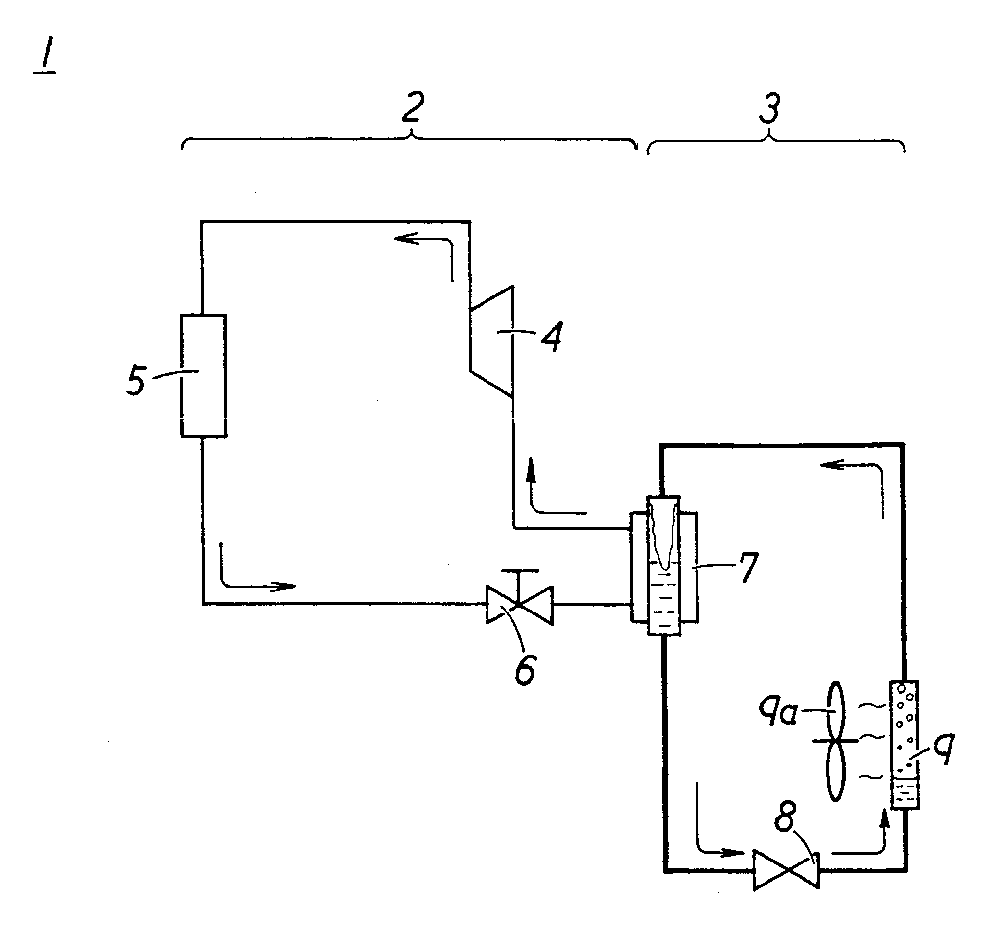
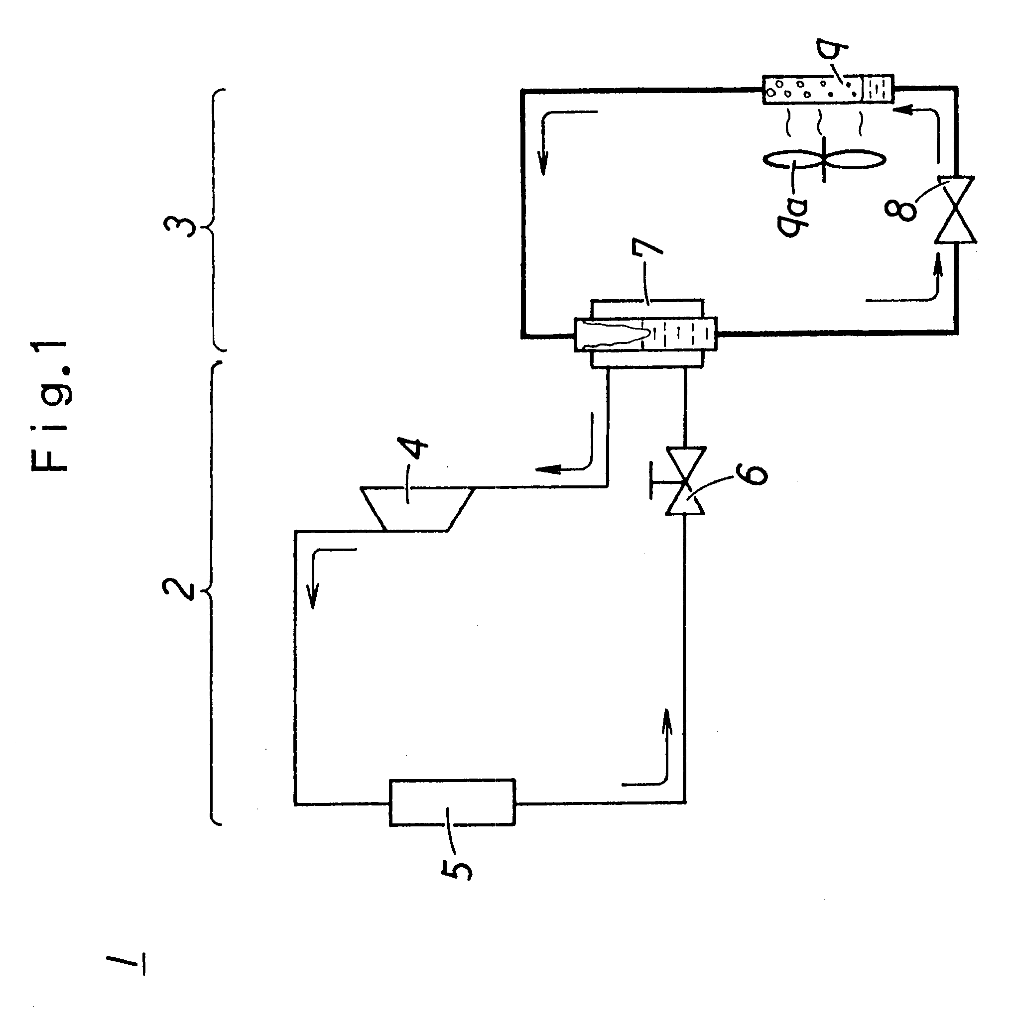
The heat pump system 1, solely carries out refrigeration, and includes an ammonia cycle 2 at an upper phase, and a carbon dioxide cycle at a lower phase as illustrated in FIG. 1.

The ammonia cycle 2 is provided, for example, with a compressor 4, a condenser 5, expansion valve 6 and a cascade condenser 7. The cascade condenser 7 practically plays the role of cooling carbon dioxide existing in the carbon dioxide cycle 3. Since the ammonia cycle 2 uses the toxic ammonia as the working medium, the minimum volume of ammonia has been filled in the ammonia cycle 2, and the structural elements of the ammonia cycle 2 are placed on a roof or at any other outdoor space, away from the corresponding evaporator incorporated in the objective showcase refrigerator.

The carbon dioxide cycle 3 is provided, for example, with the cascade condenser 7 as above discussed, and a flow adjust valve 8 and an evaporator 9. For example, the flow adjust valve 8 and the evaporator 9 are, or only the evaporator 9 i...

second embodiment

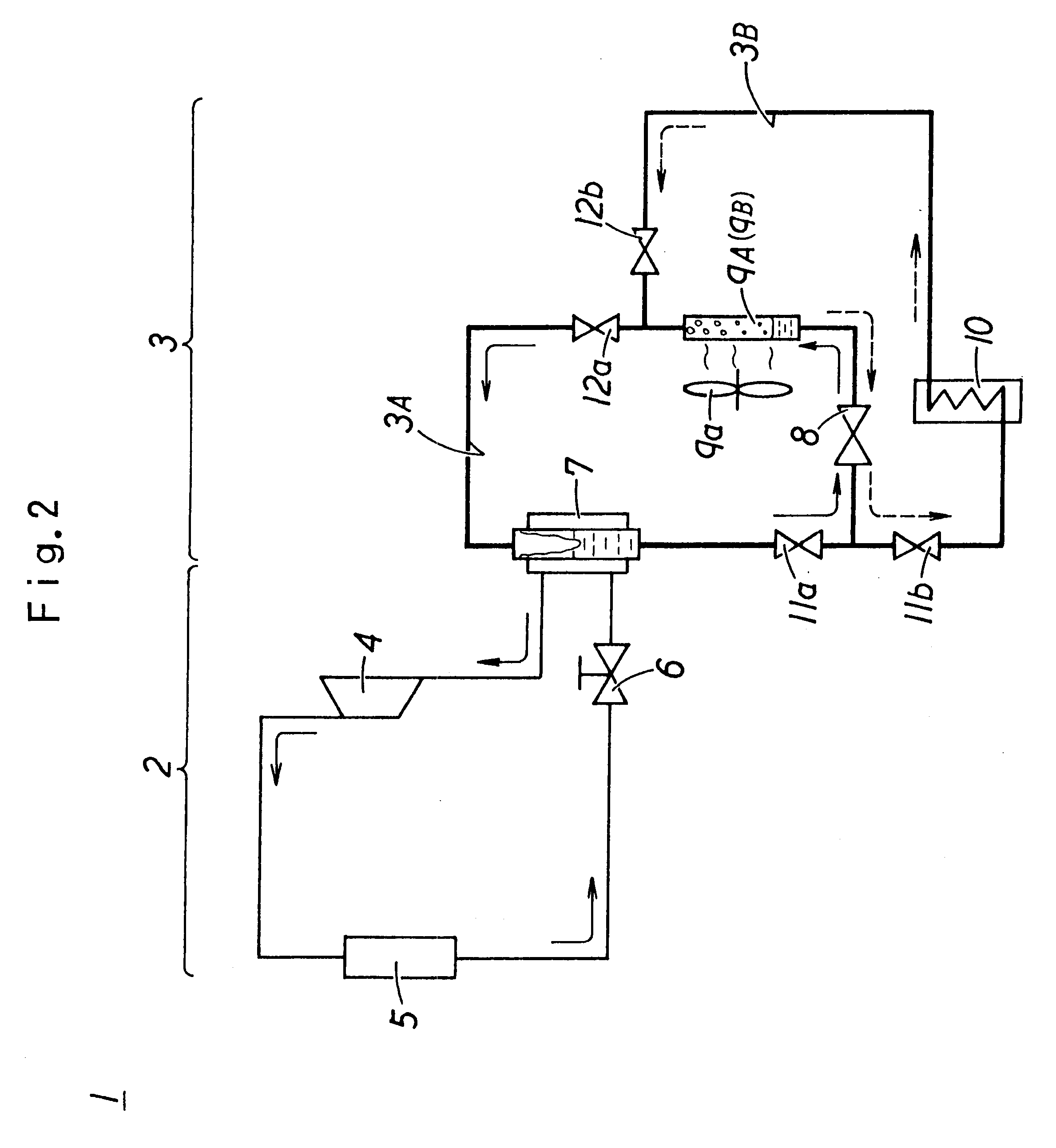
The second embodiment of the present invention will now be described. The heat pump system 1 according to the second embodiment selectively carries out either refrigeration or heating, by combing the ammonia cycle 2 and the carbon dioxide cycle 3 as illustrated in FIG. 2. The ammonia cycle 2 is substantially the same as that of the first embodiment, so the detailed explanation thereof will not be made here, and the carbon dioxide gas cycle 3 will be discussed in detail.

The carbon dioxide cycle 3 comprises a carbon dioxide refrigeration cycle 3A functioning during cooling and a carbon dioxide heating cycle 3B functioning during heating. The structure of carbon dioxide refrigeration cycle 3A is substantially the same as that of the first embodiment, provided with the cascade condenser 7, the flow adjust valve 8 and the evaporator 9A. The carbon dioxide heating cycle 3B is provided with the flow adjust valve 8, a radiator 9B and a heat absorbing device 10. The heat absorbing device 10 ...


PUM


Abstract

A heat pump system for cooling (refrigeration) or heating is provided by employing a combination of natural media such as ammonia and CO2. The heat pump system (1) combines an ammonia cycle (2) and a CO2 cycle (3), and the CO2 medium in the CO2 cycle (3) is circulated, by natural circulation due to a difference of fluid heads of the CO2 medium in the cycle without the necessity of incorporating a compressor, and by partial heating or cooling of the cycle. The structural elements of the ammonia cycle (2) are located away from the devices for the desired refrigeration and heating.

Description

1. Technical FieldThe present invention relates to a heat pump system in which natural media are employed. More particularly, the present invention relates to a heat pump system using natural media such as ammonia and carbon dioxide and simultaneously accomplishing the economical utility.2. Description of Related ArtRecently there have been resolutions made at Montreal (Montreal Protocol) and Kyoto (Kyoto Protocol to the United Nations Framework Convention on Climate Change), of which the objective is the disuse or reduction of several types of refrigerant such as chlorofluorocarbon (CFC), hydrochlorofluorocarbon (HCFC) or hydrofluorocarbon (HFC), in order to prevent the ozone layer destruction around the earth or Global Warming. In Japan, CFC, HCFC and HFC are collectively abbreviated as "flon" gas, respectively referred to as "specified flon," "designated flon" and "alternative flon," and their restriction is now under development. CFC has become disused in the end of 1995. HCFC i...

Claims


Application Information

Patent Timeline
Patent Type & Authority Patents(United States)
IPC IPC(8): F25B25/00F25B9/00F25B23/00
CPCF25B25/005F25B9/008F25B23/006F25B2309/06F25B2400/22
Inventor KANEO, HIDETOSHI
Owner HACHIYO ENG CO LTD
Why Eureka
Try Eureka