Method of and system for producing images of objects using planar laser illumination beams and image detection arrays

a technology of image detection array and laser illumination beam, which is applied in the direction of electromagnetic radiation sensing, exposure control, instruments, etc., can solve the problems of large, heavy and expensive, and the balance of output illumination power is simply wasted in heat, and achieves the effect of avoiding shortcomings

Inactive Publication Date: 2003-10-07
METROLOGIC INSTR
View PDF30 Cites 61 Cited by
  • Summary
  • Abstract
  • Description
  • Claims
  • Application Information

AI Technical Summary

Benefits of technology

Accordingly, a primary object of the present invention is to provide an improved method of and system for illuminating the surface of objects during image formation and detection operations and also improved methods of and systems for producing digital images using such improved methods of object illumination, while avoiding the shortcomings and drawbacks of prior art systems and methodologies.
FIG. 29 is a schematic representation of an exemplary Photo-integration Time Period Look-Up Table associated with CCD image detection array employed in the Auto-Focus / Auto-Zoom Digital Camera Subsystem of the PLIIM-based system, wherein for a given detected package height and package velocity, the Camera Control Computer uses the Look-Up Table to determine the precise photo-integration time period for the CCD image detection elements employed within the Auto-Focus / Auto-Zoom Digital Camera Subsystem (i.e. the IFD module) so that the camera subsystem automatically captures focused digital images having (1) square pixels (i.e. 1:1 aspect ratio) independent of package height or velocity, (2) significantly reduced speckle-noise levels, and (3) constant image resolution measured in dots per inch (DPI) independent of package height or velocity;

Problems solved by technology

Most prior art CCD-based image scanners, employed in conveyor-type package identification systems, require high-pressure sodium, metal halide or halogen lamps and large, heavy and expensive parabolic or elliptical reflectors to produce sufficient light intensities to illuminate the large depth of field scanning fields supported by such industrial scanning systems.
The balance of the output illumination power is simply wasted in the form of heat.
However, even with such improvements in LED illumination techniques, the working distance of such hand-held CCD scanners can only be extended by using more LEDs within the scanning head of such scanners to produce greater illumination output therefrom, thereby increasing the cost, size and weight of such scanning devices.
Similarly, prior art "hold-under" and "hands-free presentation" type CCD-based image scanners suffer from shortcomings and drawbacks similar to those associated with prior art CCD-based hand-held image scanners.

Method used


Image

  • Method of and system for producing images of objects using planar laser illumination beams and image detection arrays
  • Method of and system for producing images of objects using planar laser illumination beams and image detection arrays
  • Method of and system for producing images of objects using planar laser illumination beams and image detection arrays

Examples


first generalized embodiment

of the PLIIM System of the Present Invention

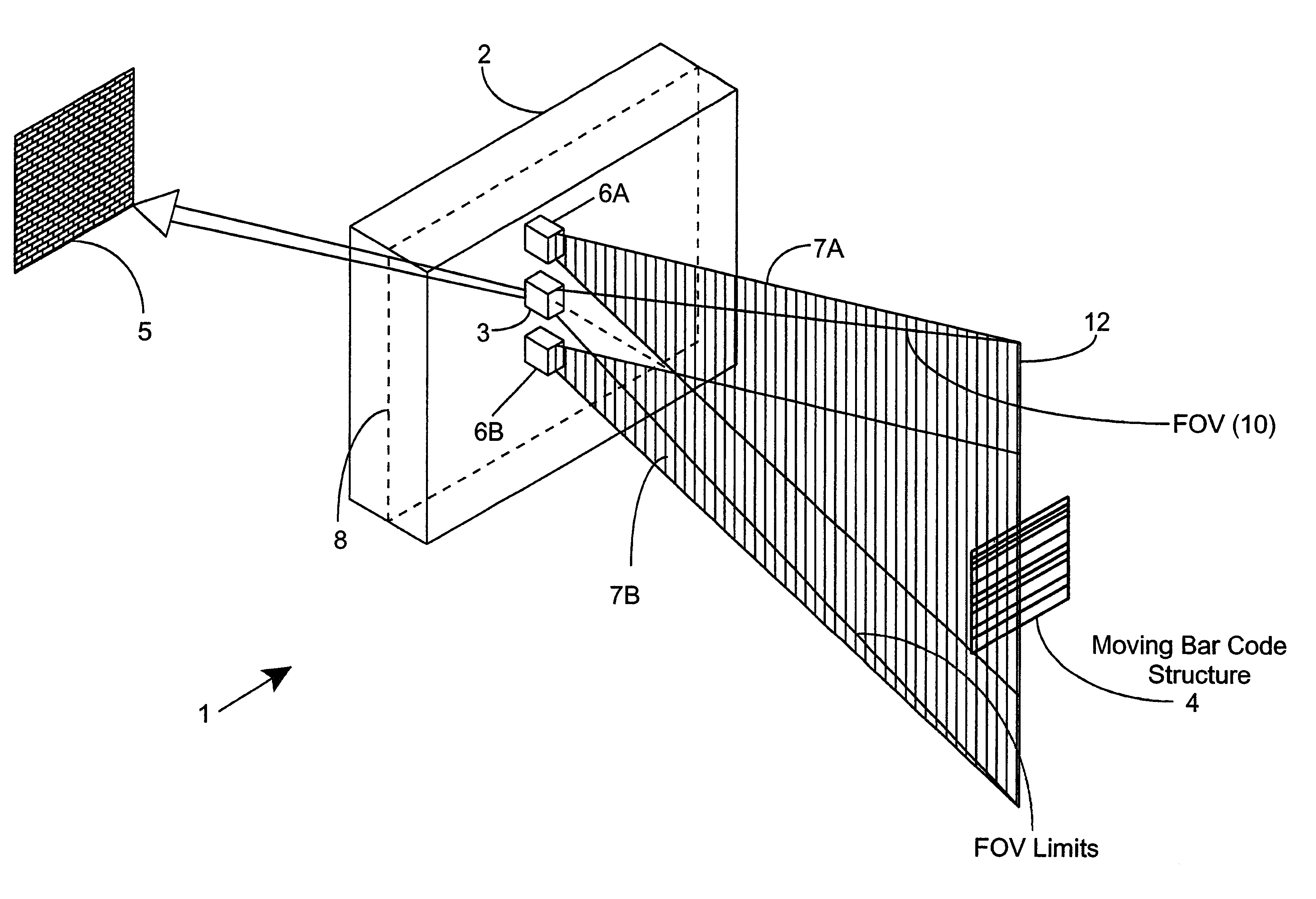
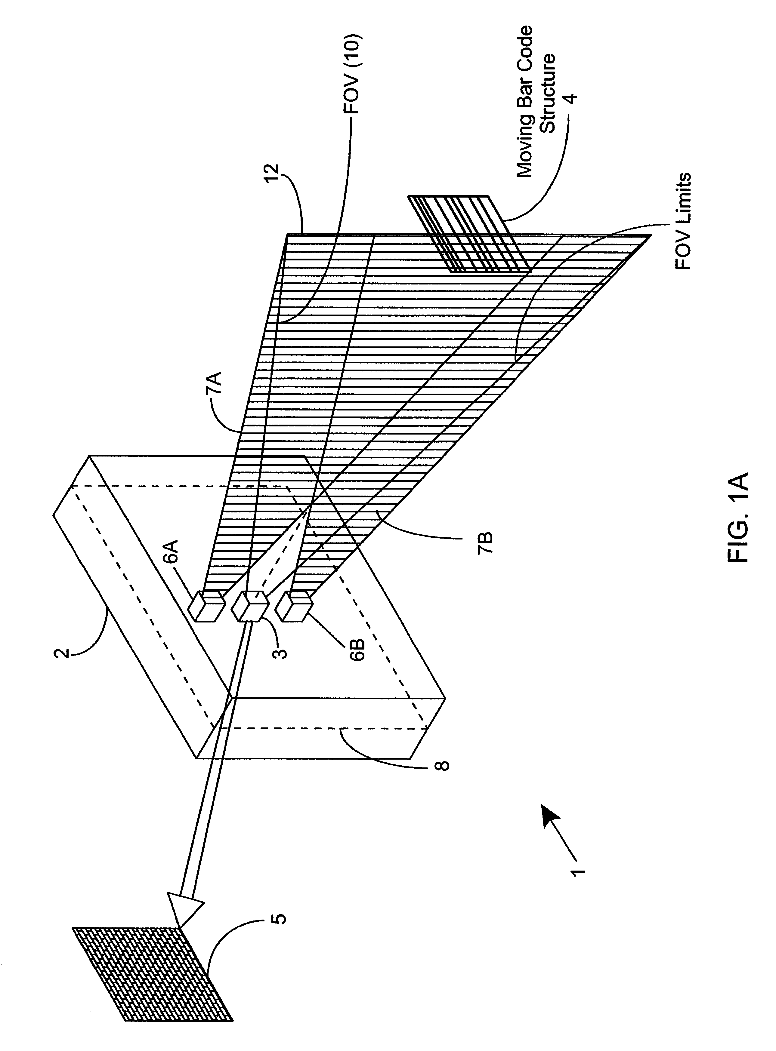
The first generalized embodiment of the PLIIM system of the present invention 1 is illustrated in FIG. 1A. As shown therein, the PLIIM system 1 comprises: a housing 2 of compact construction; a linear (i.e. 1-dimensional) type image formation and detection (IFD) 3 including a 1-D electronic image detection array 3A, and a linear (1-D) imaging subsystem (LIS) 3B having a fixed focal length, a fixed focal distance, and a fixed field of view (FOV), for forming a 1-D image of an illuminated object 4 located within the fixed focal distance and FOV thereof and projected onto the 1-D image detection array 3A, so that the 1-D image detection array 3A can electronically detect the image formed thereon and automatically produce a digital image data set representative of the detected image for subsequent image processing; and a pair of planar laser illumination arrays (PLIAs) 6A and 6B, each mounted on opposite sides of the IFD module 3, such that ea...

third generalized embodiment

of the PLIIM System of the Present Invention

The third generalized embodiment of the PLIIM system of the present invention 40 is illustrated in FIG. 2A. As shown therein, the PLIIM system 40 comprises: a housing 2 of compact construction; a linear (i.e. 1-dimensional) type image formation and detection (IFD) module 3' including a 1-D electronic image detection array 3A, a linear (1-D) imaging subsystem (LIS) 3B' having a fixed focal length, a variable focal distance, and a fixed field of view (FOV), for forming a 1-D image of an illuminated object located within the fixed focal distance and FOV thereof and projected onto the 1-D image detection array 3A, so that the 1-D image detection array 3A can electronically detect the image formed thereon and automatically produce a digital image data set 5 representative of the detected image for subsequent image processing; and a pair of planar laser illumination arrays (PLIAs) 6A and 6B, each mounted on opposite sides of the IFD module 3', s...

fourth generalized embodiment

of the PLIM System of the Present Invention

The fourth generalized embodiment of the PLIIM system 40' of the present invention is illustrated in FIGS. 2I1 and 2I2. As shown in FIG. 2I1, the PLIIM system 40' comprises: a housing 2 of compact construction; a linear (i.e. 1-dimensional) type image formation and detection (IFD) module 3'; and a pair of planar laser illumination arrays (PLIAs) 6A and 6B mounted on opposite sides of the IFD module 3'. During system operation, laser illumination arrays 6A and 6B each produce a moving planar laser illumination beam 12' which synchronously moves and is disposed substantially coplanar with the field of view (FOV) of the image formation and detection module 3', so as to scan a bar code symbol or other graphical structure 4 disposed stationary within a 3-D scanning region.

As shown in FIGS. 2I2 and 2I3, the PLIIM system of FIG. 2I1 comprises: an image formation and detection module 3' having an imaging subsystem 3B' with a fixed focal length imag...


PUM


Abstract

Methods of and systems for illuminating objects using planar laser illumination beams having substantially-planar spatial distribution characteristics that extend through the field of view (FOV) of image formation and detection modules employed in such systems. Each planar laser illumination beam is produced from a planar laser illumination beam array (PLIA) comprising an plurality of planar laser illumination modules (PLIMs). Each PLIM comprises a visible laser diode (VLD, a focusing lens, and a cylindrical optical element arranged therewith. The individual planar laser illumination beam components produced from each PLIM are optically combined to produce a composite substantially planar laser illumination beam having substantially uniform power density characteristics over the entire spatial extend thereof and thus the working range of the system. Preferably, each planar laser illumination beam component is focused so that the minimum beam width thereof occurs at a point or plane which is the farthest or maximum object distance at which the system is designed to acquire images, thereby compensating for decreases in the power density of the incident planar laser illumination beam due to the fact that the width of the planar laser illumination beam increases in length for increasing object distances away from the imaging optics. By virtue of the present invention, it is now possible to use both VLDs and high-speed CCD-type image detectors in conveyor, hand-held and hold-under type scanning applications alike, enjoying the advantages and benefits that each such technology has to offer, while avoiding the shortcomings and drawbacks hitherto associated therewith.

Description

1. Technical FieldThe present invention relates generally to an improved method of and system for illuminating the surface of objects during image formation and detection operations, and also to an improved method of and system for producing digital images using such improved methods of object illumination.2. Brief Description of the Prior ArtThe use of image-based bar code symbol readers and scanners is well known in the field of auto-identification. Examples of image-based bar code symbol reading / scanning systems include, for example, hand-hand scanners, point-of-sale (POS) scanners, and industrial-type conveyor scanning systems.Presently, most commercial image-based bar code symbol readers are constructed using charge-coupled device (CCD) image sensing / detecting technology. Unlike laser-based scanning technology, CCD imaging technology has particular illumination requirements which differ from application to application.Most prior art CCD-based image scanners, employed in conveyo...

Claims


Application Information

Patent Timeline
Patent Type & Authority Patents(United States)
IPC IPC(8): G02B26/10G02B27/48G06K7/10H01S5/40H01S5/022H01S5/00
CPCB82Y15/00G02B26/10G02B27/48G06K7/10732G06K7/10811G06K7/10722H01S5/4025H01S5/02248H01S5/02325
Inventor TSIKOS, CONSTANTINE J.SCHNEE, MICHAEL D.ZHU, XIAOXUNAMUNDSEN, THOMASNAYLOR, CHARLES A.DOBBS, RUSSELL JOSEPHWIRTH, ALLANJANKEVICS, ANDREWKNOWLES, CARL HARRY
Owner METROLOGIC INSTR
Why Eureka
Try Eureka