Image processing system and method for removing or compensating for diffraction spots

a technology of image processing and spot detection, applied in the direction of direction finders using electromagnetic waves, photometry, direction finders, etc., can solve the problems of false target detection, increased noise, and false spot detection

Inactive Publication Date: 2003-10-07
BAE SYSTEMS PLC
View PDF9 Cites 10 Cited by
  • Summary
  • Abstract
  • Description
  • Claims
  • Application Information

AI Technical Summary

Problems solved by technology

Due to diffraction scatter and emission by the grid, there is the potential problem of increased noise due to the provision of the grid compared to a window comprising only an optical substrate.
In some circumstances, even when the actual source of radiation is outside the field of view of the optical equipment associated with the sensor, some false spots can be detected.
Where the window of this type is used with a target detection system, this can lead to detection of a false target.

Method used


Image

  • Image processing system and method for removing or compensating for diffraction spots
  • Image processing system and method for removing or compensating for diffraction spots
  • Image processing system and method for removing or compensating for diffraction spots

Examples


Embodiment Construction

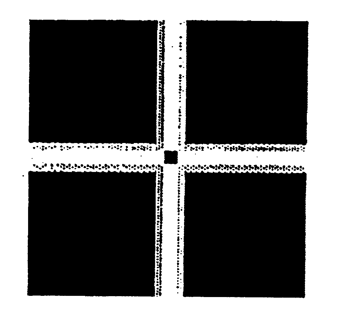
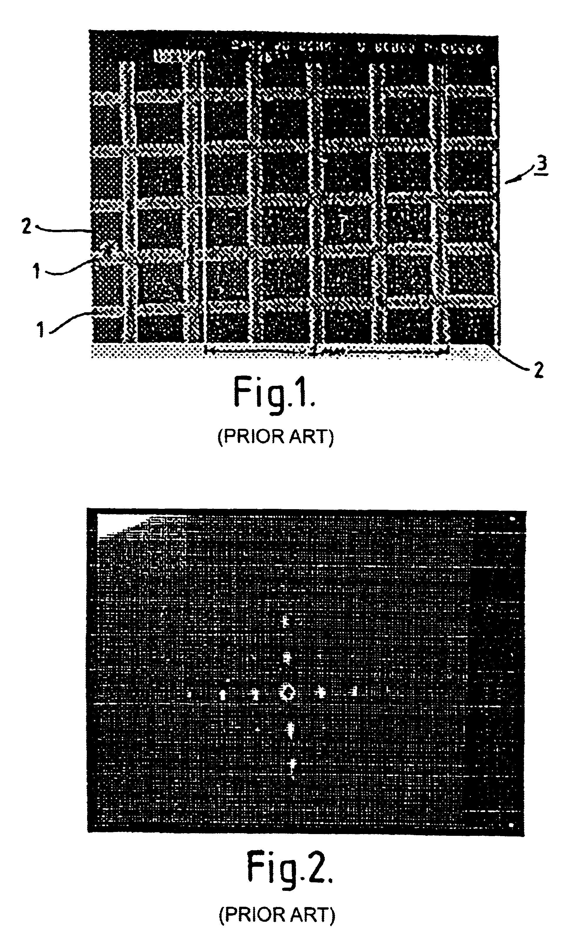
As shown in FIG. 1, a conventional optical window 3 includes a regular conductive mesh formed by a number of parallel and perpendicularly extending linear conductors 1 formed on an optically transparent substrate 2.

As shown in FIG. 2, when an intense source of radiation is incident upon the optical window, the grid acts as a two-dimensional diffraction grating, and accordingly, in addition to the actual image of the source of radiation, a number of false images will be observed. These will be in a two-dimensional pattern with respect to the real image.

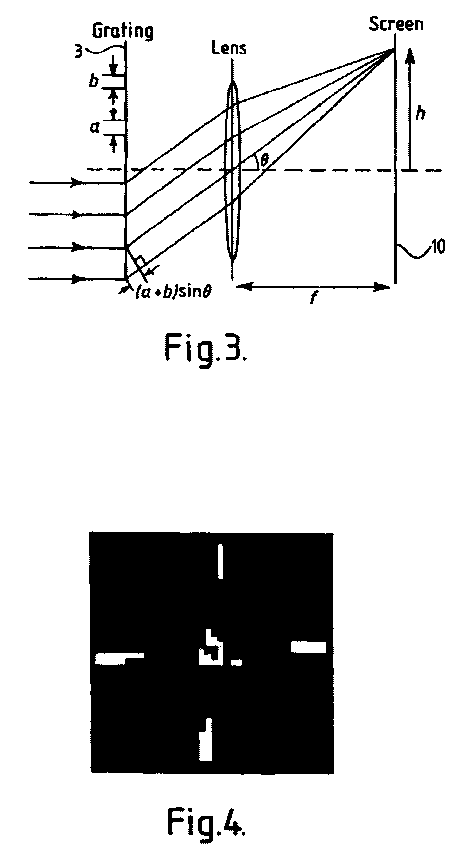
According to one example of the present invention, as shown schematically in FIG. 3, a charge coupled device 10 is provided behind the optical window 3. When a source emits radiation which is incident on the optical window 3, the radiation is transmitted through the window producing a real image on the charge coupled device 10 corresponding to the source of radiation, and a number of false images due to the diffraction effect of the me...


PUM


Abstract

Method and apparatus for determining the location at which radiation is incident on the sensor system which includes an EMI screening mesh by comparing the actual image detected, which includes the higher order diffraction effects, with a search or sample image applied sequentially at different locations and determing the location of the sample image which gives the closest match. The sample image corresponds to an expected pattern or image from a point source incident at a particular location on a particular window/sensor system, and may be generated from a real source of known location and properties incident on the system, or may be a generated image, such as a standard image such as a cross pattern or determined mathematically, for example using Fourier transforms. Preferably, once the location of the point of incidence of the radiation has been determined, image processing techniques are applied to remove the diffraction spots.

Description

1. Field of the InventionIn many imaging and detection systems for the imaging or detection of a source of electromagnetic radiation, it is desirable to provide an optical window which allows the transmission of the radiation of interest, but which provides electromagnetic interference (EMI) shielding and / or gives a low radar signature to help prevent detection of the optical aperture. Systems where such optical windows are provided include military platforms where it is desirable that the platform be hard to detect by radar, and in particular to target detection systems provided in such platforms, and to all forms of sensor or electrical systems which are sensitive to electro-magnetic interference.2. Discussion of Prior ArtKnown windows for use in such applications include those formed from a bulk semiconductor substrate, those coated with a continuous semiconductor or metallic coating, those formed as free-standing meshes and those formed as metallic meshes deposited on an optical...

Claims


Application Information

Patent Timeline
Patent Type & Authority Patents(United States)
IPC IPC(8): G01S3/781G01S3/78
CPCG01S3/781G01S3/7803
Inventor FINN, HARRY J
Owner BAE SYSTEMS PLC
Why Eureka
Try Eureka