
System and method for quantifying material properties

a material property and measurement system technology, applied in the direction of mechanical measurement arrangement, simultaneous indication of multiple variables, instruments, etc., can solve the problems of reducing the value of test data with the time it takes, and affecting the accuracy of measurement results. , to achieve the effect of optimizing the overall economy and utility, reducing the number of mechanical testing methods, and simplifying mechanical testing methods

Inactive Publication Date: 2003-10-14
SEALE JOSEPH B
View PDF8 Cites 44 Cited by
  • Summary
  • Abstract
  • Description
  • Claims
  • Application Information

AI Technical Summary

Benefits of technology

In another embodiment, it is an object to provide mechanical testing means that imposes varying influences such as stresses and temperature conditions upon one or more material samples over time, those conditions probing the range of properties associated with the model parameters, such that the information processing system can reliably and accurately resolve those parameters from the test data. It is a related object to simplify the mechanical testing means, and to minimize the number of samples of a given material required for a characterization, and to abbreviate the time period required for characterization, in order to optimize the overall economy and utility of the mechanical testing means and associated information system, consistent with the overall system yielding accurate characterizations of materials over a usefully broad range of dynamic conditions.

Problems solved by technology

Creep properties are less often determined, since the testing is time-consuming.
The traditional tests described above, usually not involving programmable test equipment, suffer from several limitations.
The longer term tests involving sustained stresses at controlled temperature tie up equipment for long periods of time.
Where process control is involved, the value of test data declines rapidly with the time it takes to obtain the data.
While impact and scratch hardness types of tests provide quick results, tests for creep properties are far too slow to provide information for tuning real-time process parameters that produce the material.
Combining test results can reveal material properties over wide-ranging conditions, but the results do not generate a predictive analytic model that could describe material response to a set of conditions outside the specific conditions of the test results.
While Sambrook et. al. contemplate measurement of a time-dependent stress / strain relationship, and while Buschmann et. al. provide programmable actuation and sensing means that could potentially explore a complex, non-linear and time-dependent stress / strain dynamic, they provide no means for extracting meaningful simplifications or descriptive parameters from the multitude of testing possibilit
The difficulty with conventional methods is the proliferation of possibilities for data collection over differing stresses, strains, temperatures, humidities, and the time-sequences involving these variables, without a method for reducing the data to a concise set of useful parameters.
As with nonlinear stress and strain in solids, a limited understanding of the dynamic properties of magnetic materials has limited the testing and characterization of these materials.
Curve fitting techniques are used to capture initial magnetization curves of virgin samples, while coercive force and saturation values are used to approximate the character of a hysteresis loop at very high cyclic excitation, but the descriptors do not predict, for example, how small hysteresis loops behave for small cyclic excitations, with or without magnetic bias.
In both solid mechanics and magnetics, very detailed models suffer from becoming too specialized, being applicable only to very particular materials under very particular conditions.

Method used


Image

  • System and method for quantifying material properties
  • System and method for quantifying material properties
  • System and method for quantifying material properties

Examples


Embodiment Construction

The preceding summary has been fairly comprehensive, implying a range of possible embodiments. The stable core of these embodiments is an original physics analysis and computational method for obtaining a meaningful and accurate approximation of complex, nonlinear, temperature dependent dynamic stress / strain responses in a wide range of materials, particularly polymers and elastomers. The invention becomes more complex when it comes to methods for error minimization to obtain an optimum parameter fit to data, with a number of preexisting methods being adaptable to the completely new context described. At the data acquisition end of the system, the possibilities take on the broadest range, with many sets of tests that probe the range of material properties being applicable. Impact and scratch or hardness tests do not probe such a range, but creep modulus tests do better. Those tests do not anticipate the utility of much shorter-term data, which can be used to broaden the range of mod...


PUM

PropertyMeasurementUnit
timeaaaaaaaaaa
timeaaaaaaaaaa
temperatureaaaaaaaaaa

Abstract

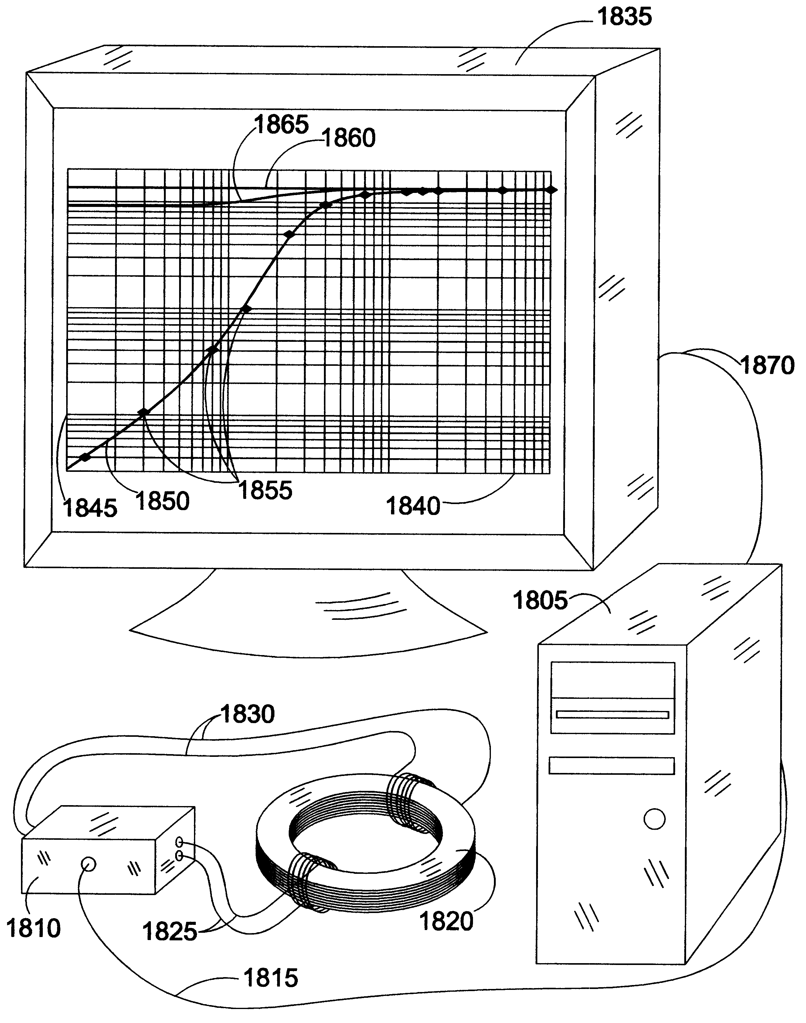
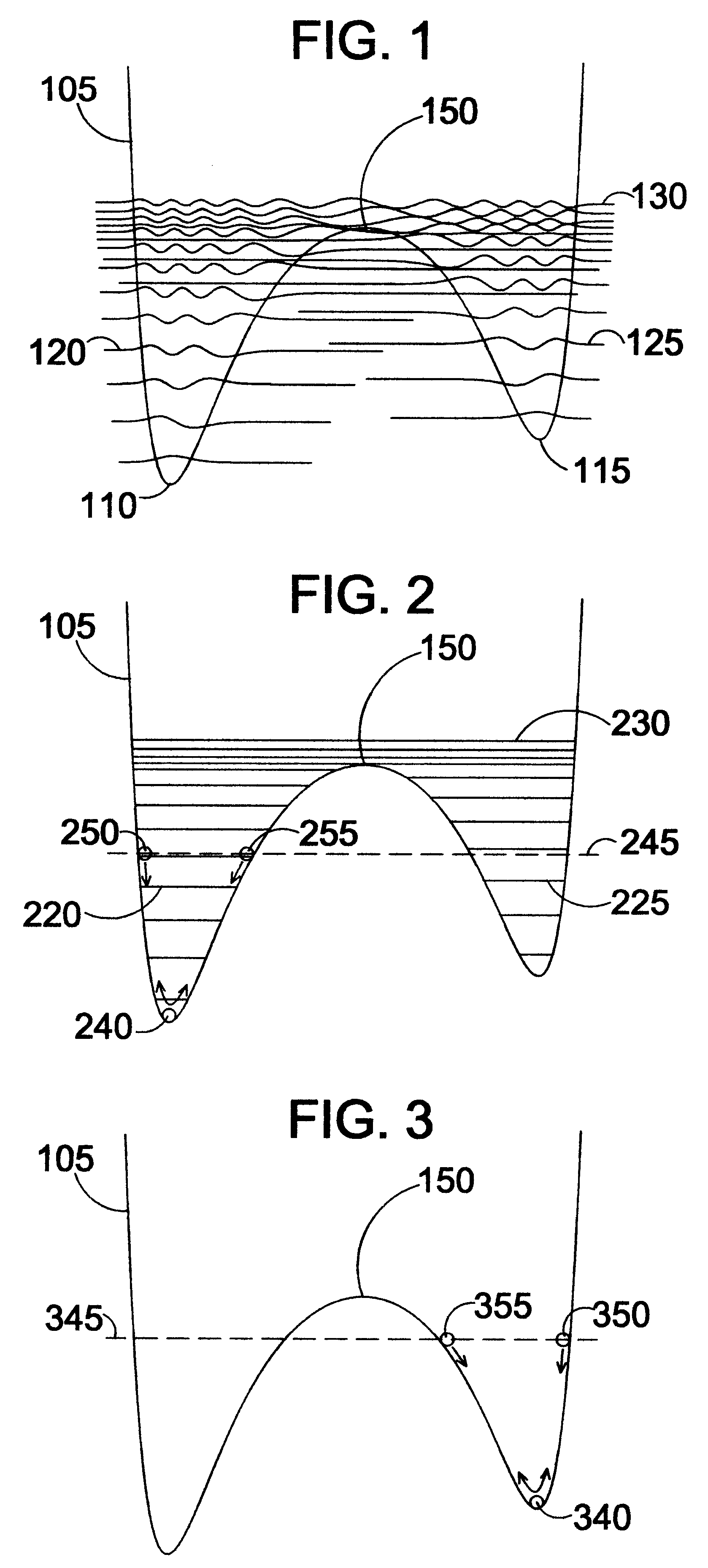
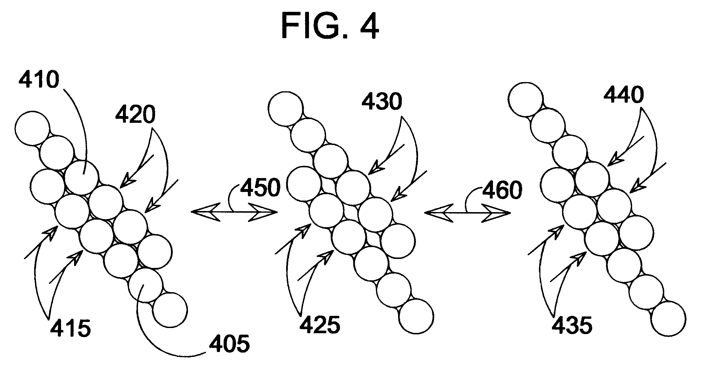
A materials characterization method models dynamic, non-linear, temperature-dependent stress, strain, hysteresis, creep, and loss of elasticity at high strain, both in test samples and in Finite Element Analysis (FEA). Incorporating universal properties of statistical mechanics and adapting domain models from ferromagnetics to the higher-dimensional realm of stress tensors, the model is applicable to polymers, rubbers, liquids, and metals in elastic and plastic deformation. The model quantifies the dynamics of both plastic and brittle failure. Apparatus and methods are shown for testing material samples and matching the computational model to sample characteristics, leading to a set of characterizing parameters and predictive simulations using those parameters. Though apparatus and testing protocols of the invention yield optimum characterizations, pre-existing data from conventional testing yield useful results.< / PTEXT>

Description

Various tests have been used to characterize the mechanical properties of material samples, particularly of polymer plastics and elastomer or rubbery materials. In one short-term category are impact tests such as Izod impact, and Durometer testing. A thin piece of material is placed on a hard surface and impacted by a hard object at varying kinetic energies until permanent deformation or rupture is observed. Other hardness tests array materials according to which material will scratch which softer material, for example, diamond scratching sapphire, sapphire scratching quartz, etc. Creep properties are less often determined, since the testing is time-consuming. Samples may be subjected to a constant stress for an extended period at a controlled temperature while strain is measured, resulting in a graph of a time-dependent modulus of elasticity, the "creep modulus," representing the ratio of stress to strain plotted as a function of time. Since strain increases over time at constant s...

Claims


Application Information

Patent Timeline
Patent Type & Authority Patents(United States)
IPC IPC(8): G01N3/00G01N3/02
CPCG01N3/00G01N2203/0071G01N2203/0222G01N2203/0214G01N2203/0218G01N2203/0075
Inventor SEALE, JOSEPH B.
Owner SEALE JOSEPH B
Learn More