Liquid crystal display device with patterned layer having fixed cholesteric order and method of manufacturing the same

a liquid crystal display and cholesteric order technology, applied in the direction of polarising elements, instruments, chemistry apparatus and processes, etc., can solve the problems of cholesteric order material losing liquid crystalline character, unable to respond to electric field, and difficult implementation of known methods, etc., to achieve accurate alignment, less non-emisive area, and tolerance tighten

Inactive Publication Date: 2003-10-21
KONINKLIJKE PHILIPS ELECTRONICS NV
View PDF13 Cites 25 Cited by
  • Summary
  • Abstract
  • Description
  • Claims
  • Application Information

AI Technical Summary

Benefits of technology

The LC device according to this aspect of the invention has a fill-factor of 85-90% compared to 70-80% for conventional LC devices. The fill-factor is the percentage of the display area actually contributing to light-emission. The large fill-factor is, on the one hand, due to the fact that the active switching elements are positioned subjacent the pixel electrodes and are rendered invisible to the viewer by the color selection layer. On the other hand, the color selection layer and the pixel electrodes being located on the same plate, remov...

Problems solved by technology

For example, in practice it has been found that the known method is difficult to implement.
Patterning at different temperatures also appears to be difficult in practice.
Being fixed, the cholesterically ordered material has lost its liquid crystalline character and is not capable any more to respond to an electric field in a manner typical of liquid crystalline materials.
Also, it does not even disclose how a patterned multi-color cholesteric layer is to be manufactured.
Being fixed, the cholest...

Method used


Image

  • Liquid crystal display device with patterned layer having fixed cholesteric order and method of manufacturing the same
  • Liquid crystal display device with patterned layer having fixed cholesteric order and method of manufacturing the same
  • Liquid crystal display device with patterned layer having fixed cholesteric order and method of manufacturing the same

Examples


example 2

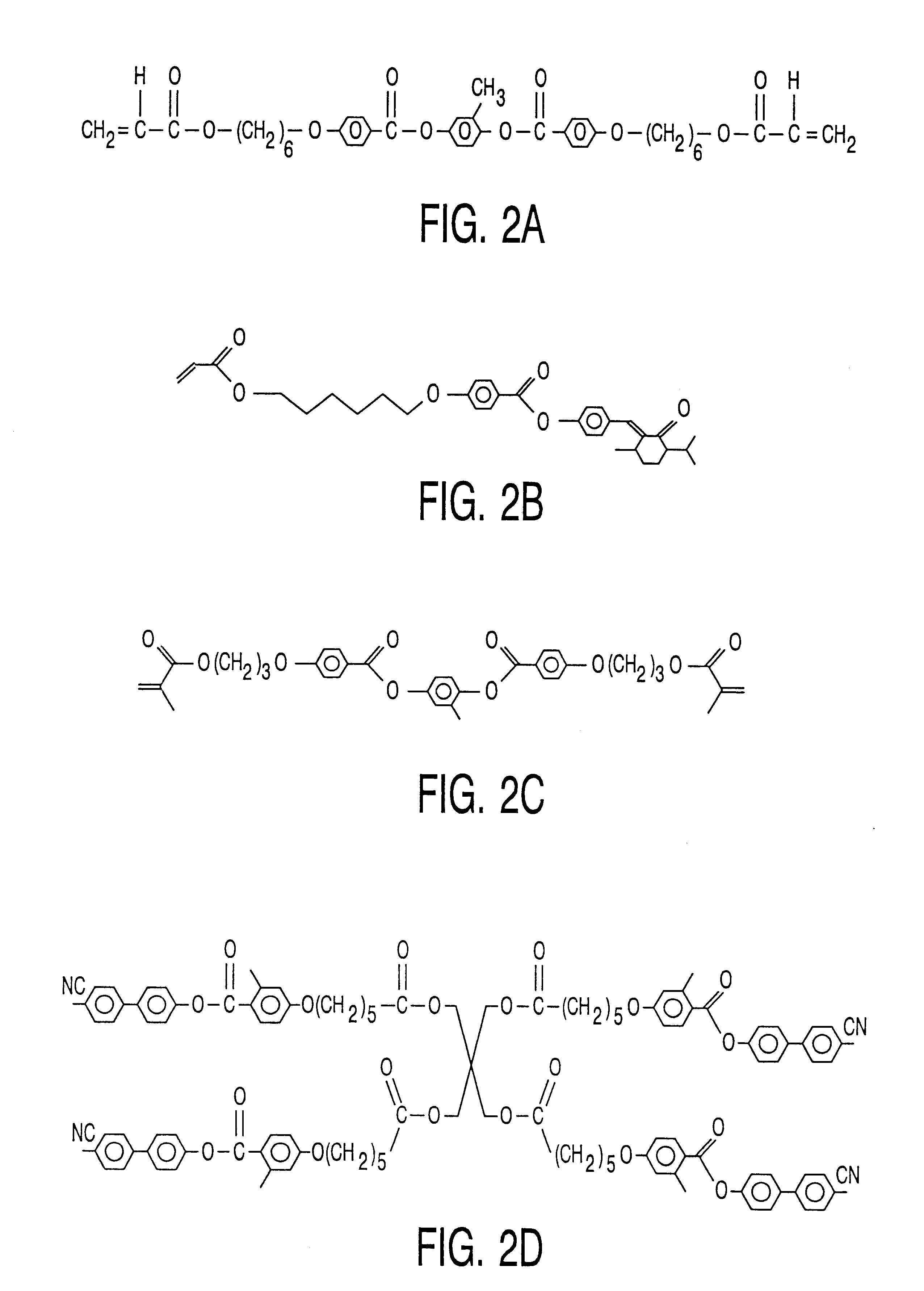
In another example, a mixture is made of 15% of compound B (RM), 84% of compound C (RM257), and 1% Darocure 4265. Darocure 4265 is a photo-initiator which can be activated using 405 nm UV radiation. Said mixture is deposited as a thin film, and subsequently, at room temperature and under ambient atmosphere (air, containing 20% oxygen), irradiated with UV light (365 nm) for a short period of time, according to a suitable pattern. During this irradiation the pitch of the molecular helix in the layer of cholesterically ordered material is altered, and the photo-initiator is activated. However, the polymerization and crosslinking of said layer is hampered because the activated initiator is quenched by the oxygen in the ambient atmosphere. After setting the required pitch, the layer is irradiated with 405 nm UV light under a nitrogen atmosphere. During this irradiation the layer is polymerized and crosslinked with substantially no change in the pitch of the molecular helix in the layer.

F...


PUM


Abstract

In a method of manufacturing a liquid crystal device including a layer having a fixed cholesteric order, the patterned layer is manufactured by providing a layer comprising polymerizable cholesterically ordered material and a compound convertible by means of radiation from a non-converted to converted state. The pitch of the cholesterically ordered material is influenced by the compound in its converted state to a different extent than in its converted state. The polymerizable layer is then irradiated pattern-wise thus creating regions of different pitch. The irradiated layer is then polymerized and/or cross-linked to fix the cholesteric order thus obtained.

Description

BACKGROUND AND SUMMARY1. Technical FieldThe invention relates to a method of manufacturing a liquid crystal display device comprising liquid crystalline material dispersed between a first and a second substrate, the first substrate comprising a patterned layer of a polymerized material having a cholesteric order wherein the axis of the molecular helix extends transversely to the layer.The invention further relates to a method of manufacturing a liquid crystal display device comprising a layer of a polymerized material having a cholesteric order wherein the axis of the molecular helix extends transversely to the layer and wherein the pitch of the helix shows exhibits a gradient in the direction along the axis.The invention also relates to a liquid crystal display device, such as one obtainable by one of the methods above.2. DescriptionA method as mentioned in the opening paragraph is known per se. For example, United Kingdom patent specification GB 2,314,167 describes a liquid crysta...

Claims


Application Information

Patent Timeline
IPC IPC(8): C09K19/58G02F1/13G02F1/1335G02B5/30G02F1/1333G02F1/1368G02B5/20G02F1/139
CPCC09K19/586G02F1/133533G02F1/133516G02F1/13
Inventor VAN DE WITTE, PETERPITT, MICHAEL GEOFFREY
Owner KONINKLIJKE PHILIPS ELECTRONICS NV
Why Eureka
Try Eureka