Cementless total replacement of the human hip joint

a total replacement and cement technology, applied in hip joints, prosthesis, medical science, etc., can solve the problems of high price of these thr's, the disadvantage of cement's application, and the inability to protect the living biomaterial from rotation in the transversal plain or from protruding vertically,

Inactive Publication Date: 2003-11-25
ZITNANSKY MARCEL +2
View PDF11 Cites 15 Cited by
  • Summary
  • Abstract
  • Description
  • Claims
  • Application Information

AI Technical Summary

Problems solved by technology

Up to now there have been known several constructions of implants for replacement of deformities or destruction of the hip joint, but each of them have, apart from certain advantages, also disadvantages.
The mentioned materials have valuable properties with high strength characteristics, low fatigue limits, abrasive resistance and are biocompatible.
These THR's present the top present state of the art in technics and scientific research in the field of implants; however, the price of these THR's is very high.
Several known THR's have the disadvantage of not being safe against rotation in the transversal plain or against protrusion in vertical direction.
Based on scientific research also the application of cement has the disadvantage of possible thermal injury to the living biomaterial during hardening.
Often there is a deficiency in securing a homogenous layer of cement around the implant in the femur by classical cementing methods.
In connection with preparing the layer of hydroxylapatite there are difficulties in binding of this layer to the metallic surface and in achieving a homogenous thin layer upon the whole functional surface.
The greatest disadvantage of the hydroxylapatite layer is the danger of releasing small particles of hydroxylapatite from the surface of the implant, which can lead to abrasion of the polyethylene part or loosening the femoral stem from the femur.
It has also been proven that while hydroxylapatite has a good bony ingrowth, by itself it creates an isolation layer with a high electrical and thermal resistance, blocking a fluent passage of biocurrents in that part of the human skeleton, causing subjective and objective difficulties for the bearer of such an implant.

Method used


Image

  • Cementless total replacement of the human hip joint
  • Cementless total replacement of the human hip joint
  • Cementless total replacement of the human hip joint

Examples


example 2

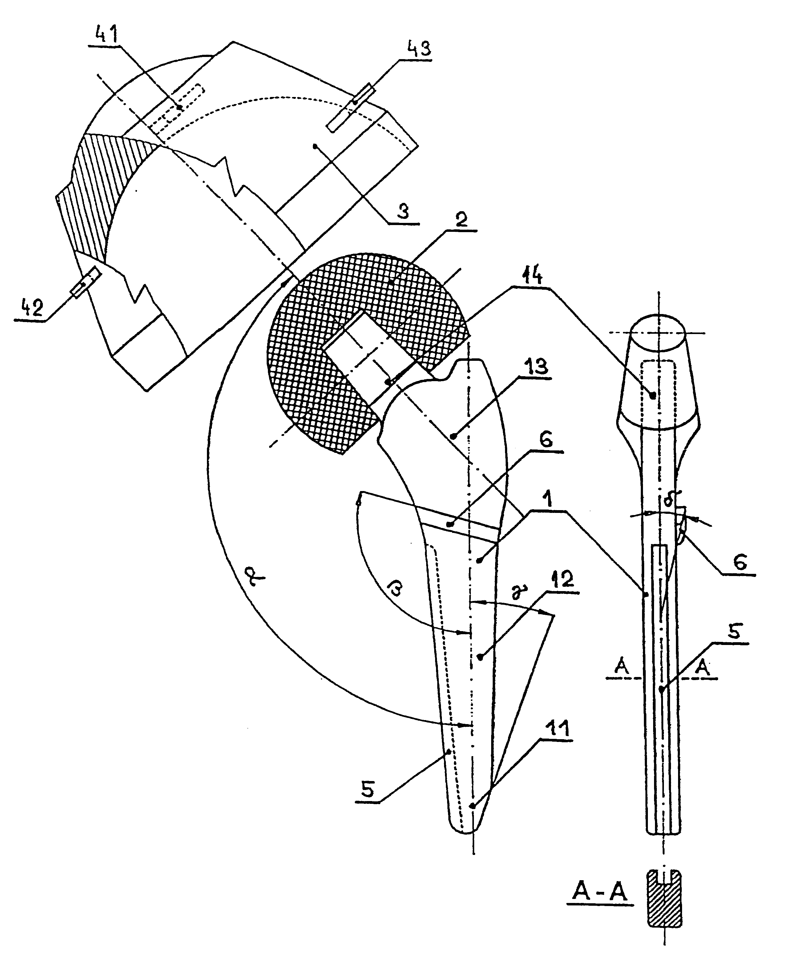
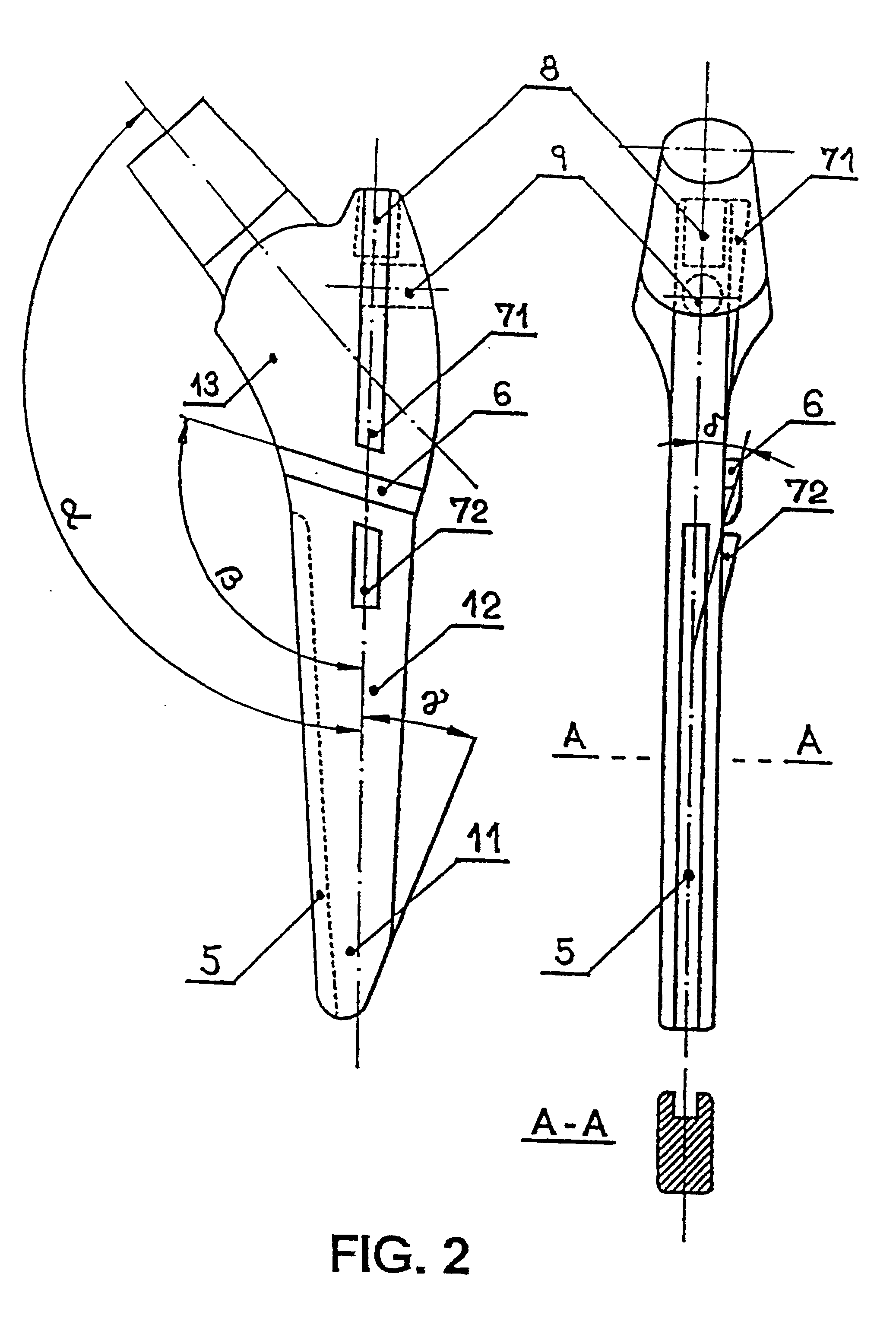
A total replacement of the human hip joint contains the acetabulum 3, which is constructed from stainless steel according to ISO 5832 / 211 whereas its shape is basically the same as in example 1 with the difference, that on its outer conical surface, which is covered with a nanocrystalline diamond layer 2 -4 nm thick, there are twelve self-drilling teeth arranged in a screwline in an angular spacing of 90.degree.. The first four teeth in the screwline (in the direction from the top of the acetabulum 3) have truncated pikes, the shape of the teeth corresponding to the embodiment in FIG. 7c, i.e. their cutting edge has a concave shape, but the 5th-12th tooth on the thread have a straight cutting edge and are sharp, i.e. have no truncated pikes (see FIG. 7a). The femoral component 1 (see FIG. 2), which is constructed from a titanium alloy of the type Ti-6Al-4V ELI contains on one main plain one 3 mm high and 3 mm wide transversal rib 6, which forms with the main axis of the wedge an ang...

example 3

The THR of the human hip joint contains an acetabulum 3 according to example 1 with the difference that all three teeth 41, 42 and 43 are sharp (shape according to FIG. 7a) and the femoral component 1 (see FIG. 3), which is constructed from stainless steel according to norm ISO 5832 / 211 and contains transversal ribs 6a, 6b, each 2 mm high and 2 mm wide, constructed on each main plain and two 3 mm high and 4 mm wide longitudinal ribs 71a, 72a, 71b, 72b made on each main plane and two grooves 5152 on the side plane in the lower part 11 and middle part 12 of the wedge 1.6 mm wide. The lower part 11, middle part 12 and the upper part 13 of the wedge are covered with a 5-8 .mu.m hydroxylapatite layer.

example 4

The total replacement of the human hip joint contains the acetabulum 3, according to FIG. 5, the outer surface of which including the self-drilling teeth 41, 42 and 43 are covered by a 3-5 .mu.m thick layer of hydroxylapatite and the femoral component 1 (see FIG. 4), which is constructed from stainless steel according to ISO 5832 / 211. The femoral component 1 contains the main body in the conical form ended in a standard cone, the axis of which forms with the main axis of the wedge an angle .alpha.=120.degree.. The wedge has on each main plain four 3 mm high and 3 mm wide longitudinal ribs 71a, 72a, 73a, 74a, 71b, 72b, 73b and 74b and three 2.5 mm high and 1.5 mm wide transversal ribs 61a, 62a, 63a, 61b, 62b and 63b which form with the main axis of the wedge an angle .beta.=100.degree.. All longitudinal ribs 71a, 72a, 73a, 74a, 71b, 72b, 73b and 74b have on the bottom end a tapering under the angle 45.degree.. The transversal ribs 61a, 62a, 63a, 61b, 62b and 63b are constructed in co...


PUM


Abstract

The solution is based on the fact, that on the surface of the acetabulum (3) there is a self-drilling thread, containing at least three independent teeth (41, 42 and 43) which advantageously have a concave shape of the cutting edge and a truncated pike, whereas the planes of their upper edges lie on a spherical surface. The femoral component (1) has on outer side of its lower part (11) an asymmetric tapering under the angle gamma=20° to 70° and on the upper part (13) a convexly widened outer side. Minimally on the lower part (11) and middle part (12) of the inner side of the femoral component (1) at least one longitudinal groove (5) is provided, and minimally on one side plane of the middle part (12) and/or of the upper part (13) there, is provided at least one transversal rib (6), forming with the axis of the wedge an angle beta=70° to 110°. At least on a part of the outer surface of the acetabulum (3) a nanocrystalline diamond or hydroxyapatite layer is preferably created and at least on a part of the outer surface of the femoral component (1) a nanocrystalline diamond and/or hydroxyapatite layer is provided.

Description

The invention concerns cementless total hip replacement prostheses (further THR) as replacement of the human hip joint applied by operation.PRIOR ARTThe term an artificial replacement of the hip joint means mostly a metallic implant and partly a non metallic implant. The replacement of a deformed hip joint by an adequate implant, constructed from special stainless biocompatible steel, cobalt or titanium alloy and nonmetallic materials is the most effective mode of eradicating the deformity or destruction of the hip joint and simultaneously a medicotechnical problem, which has been actual practically since 1923 until now and has not been solved satisfactorily by any prevention (Smith-Petersen, M. V.: Evolution of mold arthroplasty of the hip. J. Bone Joint.Surg.1949, 30B:59-75).Up to now there have been known several constructions of implants for replacement of deformities or destruction of the hip joint, but each of them have, apart from certain advantages, also disadvantages. The w...

Claims


Application Information

Patent Timeline
Patent Type & Authority Patents(United States)
IPC IPC(8): A61F2/32A61F2/00A61F2/30
CPCA61F2/30771A61F2/32A61F2250/0058A61F2002/30535
Inventor ZITNANSKY, MARCELREHAK, LUBOSMAKAI, FRANTISEK
Owner ZITNANSKY MARCEL
Why Eureka
Try Eureka