Eureka AIR delivers breakthrough ideas for toughest innovation challenges, trusted by R&D personnel around the world.

Twist drill and method of drilling composite materials, use and method regrinding and manufacturing thereof

a twist drill and composite material technology, applied in the direction of twist drills, turning machine accessories, manufacturing tools, etc., can solve the problems of notoriety of difficulty in drilling, poor quality of exit holes in conventional drills, and difficulty in manufacturing twist drills with variable helixes, etc., to achieve excellent hole size spread, simple geometry, and good drilling

Active Publication Date: 2017-03-21
SANDVIK INTELLECTUAL PROPERTY AB
View PDF23 Cites 0 Cited by
  • Summary
  • Abstract
  • Description
  • Claims
  • Application Information

AI Technical Summary

Benefits of technology

[0008]At its most general, the present invention proposes that, surprisingly, excellent hole size spread, exit hole quality and tool life in fibre reinforced composite materials including CFRP and the like can be achieved with a twist drill having a comparatively simple geometry comprising the following features: a constant helix having a comparatively large helix angle, a small point angle and a large secondary chisel angle.
[0009]Twist drills embodying this combination of constant large helix, small point angle and a large secondary chisel angle have, as shown herein, good tool life, can be easily manufactured, and produce holes with exit holes having minimal defects and hole size spread with good tolerance.

Problems solved by technology

Fibre-containing composite materials such as CFRP and GFRP represent a particular challenge, especially in terms of good hole quality.
These composite materials, particularly CFRP with twill fibre, unidirectional fibre layout, and materials with a glass cloth on the exit face, are notoriously difficult to drill and poor exit hole quality is the norm with conventional drills.
However, a twist drill having a variable helix can be complex to manufacture.

Method used


Image

  • Twist drill and method of drilling composite materials, use and method regrinding and manufacturing thereof
  • Twist drill and method of drilling composite materials, use and method regrinding and manufacturing thereof
  • Twist drill and method of drilling composite materials, use and method regrinding and manufacturing thereof

Examples


Embodiment Construction

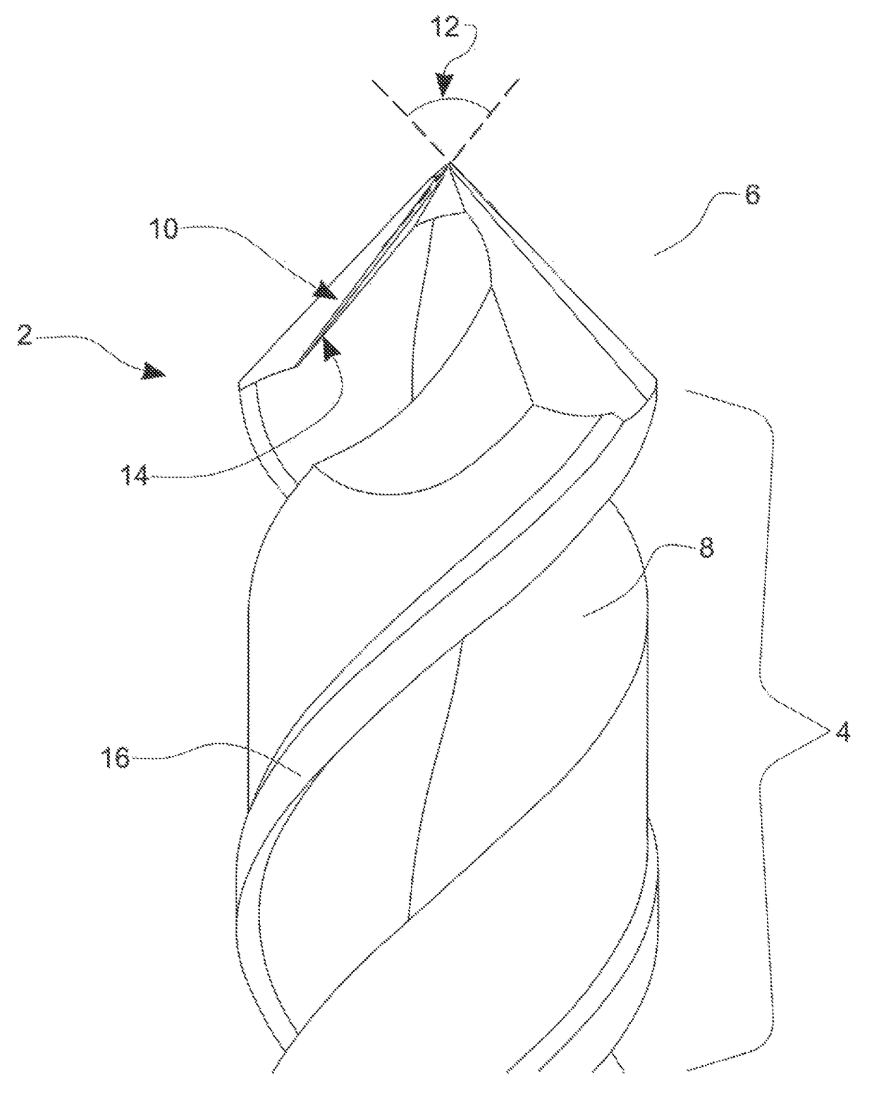
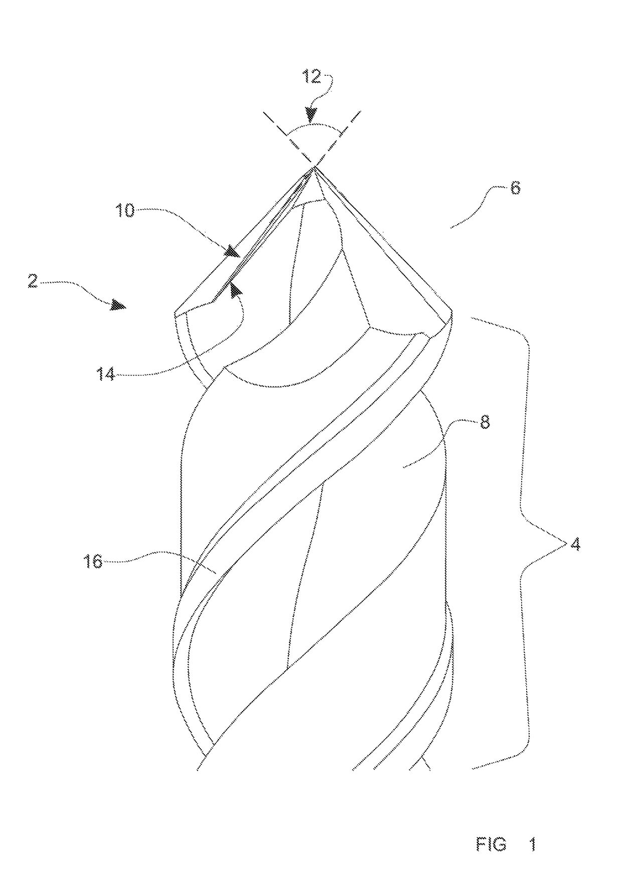
[0120]FIG. 1 shows a twist drill 2 of the present invention. The drill comprises a shank (not shown), drill body 4 and drill tip 6. Two helical flutes 8 extend from the drill tip to the drill body. The helix angle is a constant helix angle of 50°, although other constant helix angles are possible, for example 45° to 55°.

[0121]The width of the flute is substantially constant along the length of the flute.

[0122]The primary and secondary cutting edges 10 (cutting lips) at the drill tip form the point, which has a point angle 12 of 85°. Other point angles are possible, for example 70° to 100°.

[0123]The cutting edge 10 of drill 2 was edge corrected to produce a straight cutting edge 10, an artefact of this edge correction can be seen in FIG. 1 as feature 14.

[0124]Drill 2 has body clearance 16 along the flutes 8.

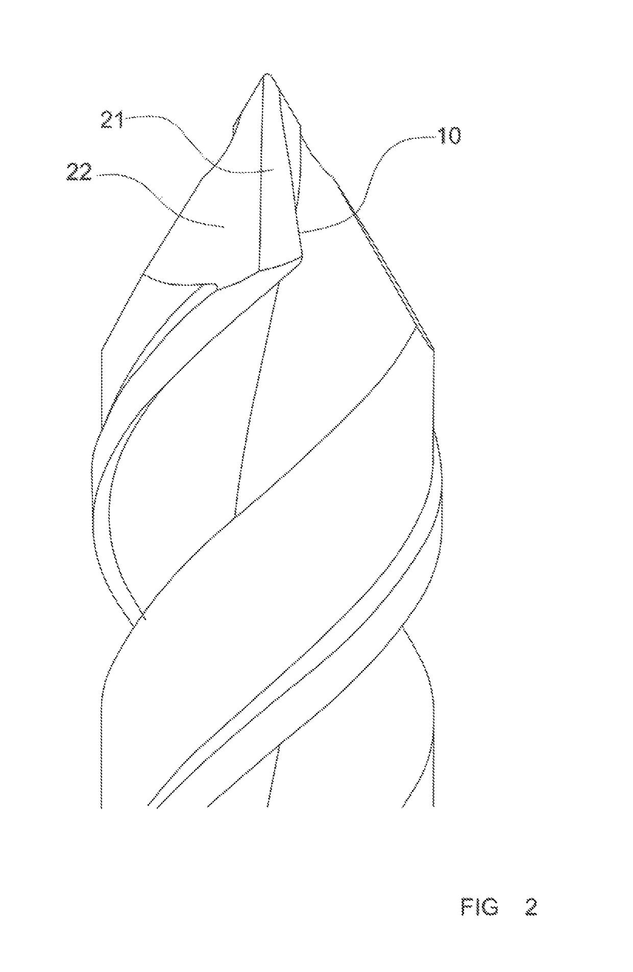
[0125]FIG. 2 shows a rotated side view of drill 2. The cutting edges of the point are provided with a primary relief 21 (also known as primary facet or flank face clearance) and s...


PUM


Abstract

A twist drill for drilling composite materials includes a shank; a drill body; a drill tip having a cutting edge, a chisel edge, and a secondary chisel edge, wherein the secondary chisel angle of the drill tip is 145° to 165 and the point angle is 70° to 100°; and a flute extending from the drill tip to the drill body. The flute has a constant helix, and the helix angle of the flute being selected from the range 45° to 55°. A method of drilling a composite material comprising fibers uses the twist drill of the present embodiment. Suitably, the composite material is carbon fiber reinforced plastic or glass fiber reinforced plastic, and optionally being a laminate material such that the method comprises stack drilling. Embodiments achieve a combination of good hole quality, good tool life and good hole size spread.

Description

RELATED APPLICATION DATA[0001]This application is a §371 National Stage Application of PCT International Application No. PCT / GB2012 / 051525 filed Jun. 29, 2012 claiming priority of GB Application No. 1111596.1, filed Jul. 6, 2011.TECHNICAL HELD OF THE INVENTION[0002]The present invention relates to twist drills and in particular twist drills adapted for drilling, especially automated drilling, of composite materials such as carbon fibre reinforced plastic (CFRP) or glass fibre reinforced plastic (GFRP).BACKGROUND[0003]Fibre-containing composite materials such as CFRP and GFRP represent a particular challenge, especially in terms of good hole quality. These materials are common materials for aircraft structure. These composite materials, particularly CFRP with twill fibre, unidirectional fibre layout, and materials with a glass cloth on the exit face, are notoriously difficult to drill and poor exit hole quality is the norm with conventional drills.[0004]Some attempts have been made t...

Claims


Application Information

Patent Timeline
Patent Type & Authority Patents(United States)
IPC IPC(8): B23B51/02B23B35/00B23P15/32B24B3/26
CPCB23B51/02B23B35/00B23P15/32B24B3/26B23B2226/275B23B2251/04B23B2251/043B23B2251/18Y10T408/03Y10T408/9097
Inventor GOH, WAN TSIN
Owner SANDVIK INTELLECTUAL PROPERTY AB
Why Eureka
Eureka Blog
Learn More