Pile array assembly system for reduced soil liquefaction

a technology of assembly system and pile array, which is applied in the direction of bulkhead/pile, foundation engineering, construction, etc., can solve the problems of not being able to predict the shape of the pile, the theory is debated and now discounted, and the pile array does not lend itself to prediction, so as to reduce the soil liquefaction and increase the ground stability

Inactive Publication Date: 2003-12-09
BERRY RICHARD M
View PDF8 Cites 36 Cited by
  • Summary
  • Abstract
  • Description
  • Claims
  • Application Information

AI Technical Summary

Benefits of technology

can be achieved with the present invention, device, assembly and system which is a pile array assembly system for use in interaction with a ground soil site and footing adjacent ...

Problems solved by technology

However, this theory is debated and now discounted by most earthquake design engineers.
It is possible that the stronger soil mass with its irregular web of lenses could deflect earthquake shock waves in some random fashion, but it would not lend itself to predictability.
However, such grout might well flare off in the soil and not result in true compaction pile shapes.
However, in individual locations, the improvement ranged from a dramatic two (2) times denser to no density improvement at all.
However, there is no way of telling whether there are meaningful effects from the specific work done.
However, the plausibility of the Ivanetich work based on its inconsistent results would not appear to be justified in relation to the realistic eventuality of the earthquake disaster anticipated in Ivanetich.
In addition, all of the relevant prior art heretofore known suffer from a number of disadvantages.
A significant shortcoming in the prior art is that it does not offer a system, adequately responsive to seismic disturbances, which appears to, both, provide adequate ground support against liquefaction and also provide the soil wit...

Method used


Image

  • Pile array assembly system for reduced soil liquefaction
  • Pile array assembly system for reduced soil liquefaction
  • Pile array assembly system for reduced soil liquefaction

Examples


Embodiment Construction

The following description of the preferred embodiments of the concepts and teachings of the present invention is made in reference to the accompanying drawing figures which constitute preselected illustrated examples and schematic representations of the elements of the present invention, among many other examples existing within the scope and spirit of the present invention.

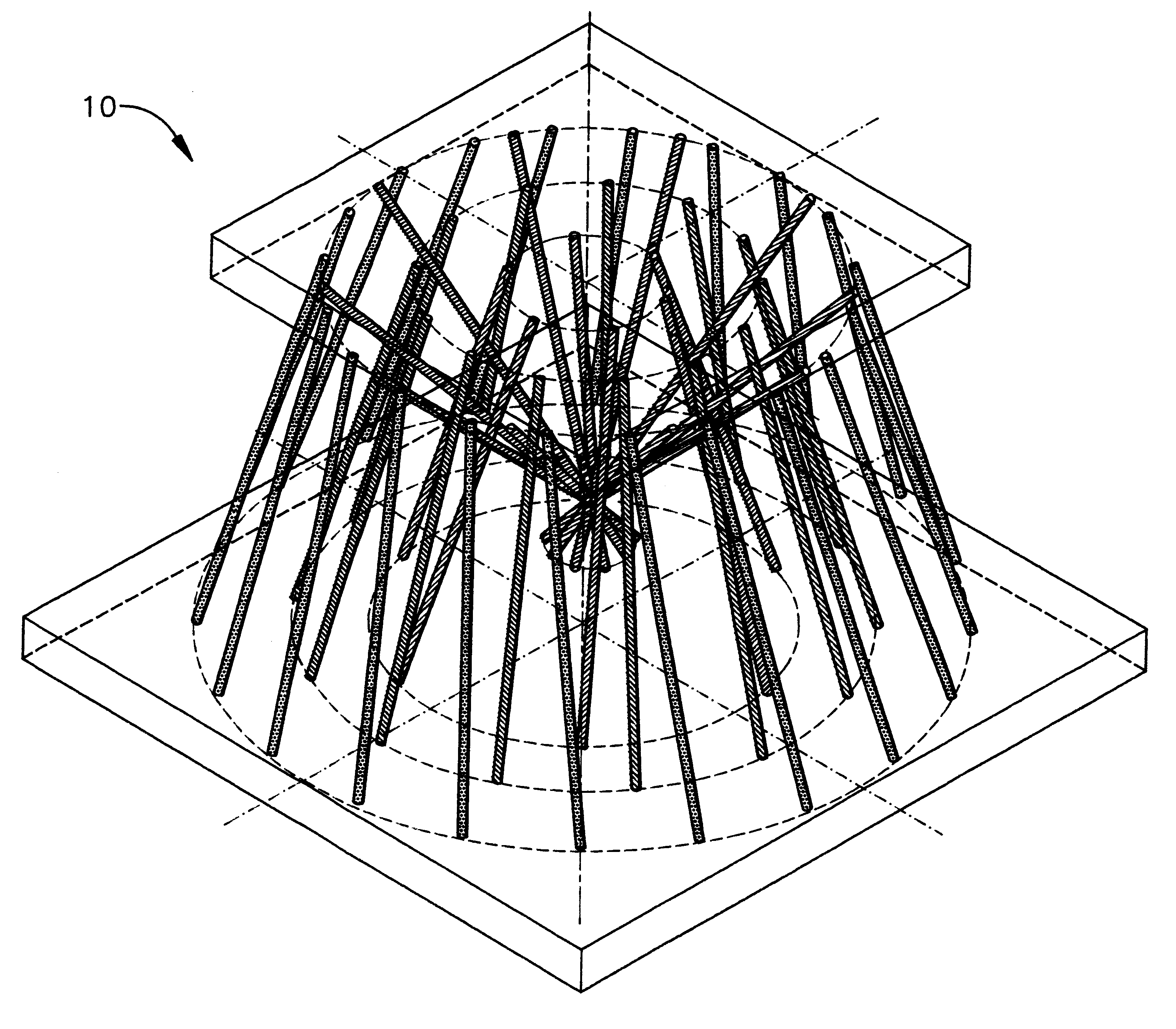
Referring now to the drawings, FIGS. 1A through 15, and 18, thereof; there is shown a Pile Array Assembly System 10 of the present invention, referred to herein as the Array 10.

The Array 10 is utilized in providing reduced soil liquefaction. In this regard, the Array 10 is utilized in interaction with ground soil through installation of the present invention at, or within, a ground site which is adjacent or proximate to footing or other preselected foundational support or architectural structures associated with ground surface buildings or other structures such as bridges, highways, road overpasses, piers, wharfs...


PUM


Abstract

A pile array assembly system for use in interaction with a ground site having adjacent building or structure footing or equivalent foundational support for reduced soil liquefaction in the event of seismic disturbance. The system is provided with a number of pile array subassemblies which relate to each other positionally and structurally to cooperate in deflecting seismic shock waves and also densifying the ground site to provide reduced soil liquefaction. Various arcuate or arc-linked pile units are placed as pile array subassemblies, in preferred embodiments, to utilize multiple configurational peripheries or perimeters of pile units. Additionally, in preferred embodiments, individual pile units within a subassembly are slanted or slanted and rotationally advanced or spun to achieve positioning for improved and advanced subground seismic wave deflection and dissipation.

Description

1. Field of The InventionThe present invention relates to apparatus, methods and assembly systems for utilizing various types of pile and grouting members to provide a special patterning and array of such members for reduced soil liquefaction in the event of earthquake or other seismic disturbance.2. Background InformationAlthough no references were found specifically relating to the vast improvements that the present invention discloses and teaches in this technology; some of the references which disclose aspects of the general technology in an experimental or theoretic sense, include United States Patents to Ringsten, U.S. Pat. No. 4,832,533; Taki, U.S. Pat. No. 5,118,223; Asayama, U.S. Pat. No. 3,975,917; Sato, U.S. Pat. No. 4,707,956; Spanovich, U.S. Pat. No. 3,464,215; and Turzillo, U.S. Pat. No. 3,886,754, and published references including Finn et al., "Liquefaction in Silty Soils: Design and Analysis," ASCE, GSP 44, October, 1994, pp. 51-78; Yourman et al., "Quality Control ...

Claims


Application Information

Patent Timeline
IPC IPC(8): E02D27/14E02D27/12E02D27/34
CPCE02D27/34E02D27/14
Inventor BERRY, RICHARD M.
Owner BERRY RICHARD M
Why Eureka
Try Eureka