System and method of reducing bearing voltage

a technology of bearing voltage and system, applied in the field of electromechanical systems, can solve the problems of increasing mechanical wear, mechanical damage to the bearing, and pitting the bearing

Inactive Publication Date: 2003-12-30
BALDOR ELECTRIC COMPANY
View PDF14 Cites 32 Cited by
  • Summary
  • Abstract
  • Description
  • Claims
  • Application Information

AI Technical Summary

Problems solved by technology

The resulting V.sub.rg gives rise to electrostatically induced I.sub.b which is a growing industry concern since such currents ultimately result in mechanical damage to the bearing.
This ultimately leads to an arcing discharge of current across the bearing, pitting the bearing and increasing mechanical wear.
This occurs when race-to-bearing asperity contacts come close, thereby increasing the oil film electric field and leading to breakdown and resulting high discharge currents.
These currents in turn create localized elevated temperatures of the races and can lead to molten pits and fluting of the outer race which in turn can lead to bearing surface damage and, ultimately, bearing failure.
These problems are often exacerbated in those cases where PWM inverters are present because PWM inverters can produce higher EDM currents than those observed during sine wave operation due to their application of high common mode voltage and thereby high V.sub.rg.
Of the solutions which have been attempted to either minimize V.sub.rg or to reduce EDM, none have been completely successful.
This approach, however, requires a low resistance contact between the brush and the rotor.
In practice such a contact is difficult to maintain due to brush wear, contamination, and surface oxidation.
Experience with conductive grease however indicates that such greases decrease bearing life dramatically.
However, this approach has raised thermal problems as rotor heat must now traverse this additional insulating layer before reaching the frame.
Use of such a shield is logistically difficult however because it must be inserted into the airgap of a motor without short circuiting the stator laminations, degrading the stator insulation system, or bridging the airgap across its entire length.

Method used


Image

  • System and method of reducing bearing voltage
  • System and method of reducing bearing voltage
  • System and method of reducing bearing voltage

Examples


Embodiment Construction

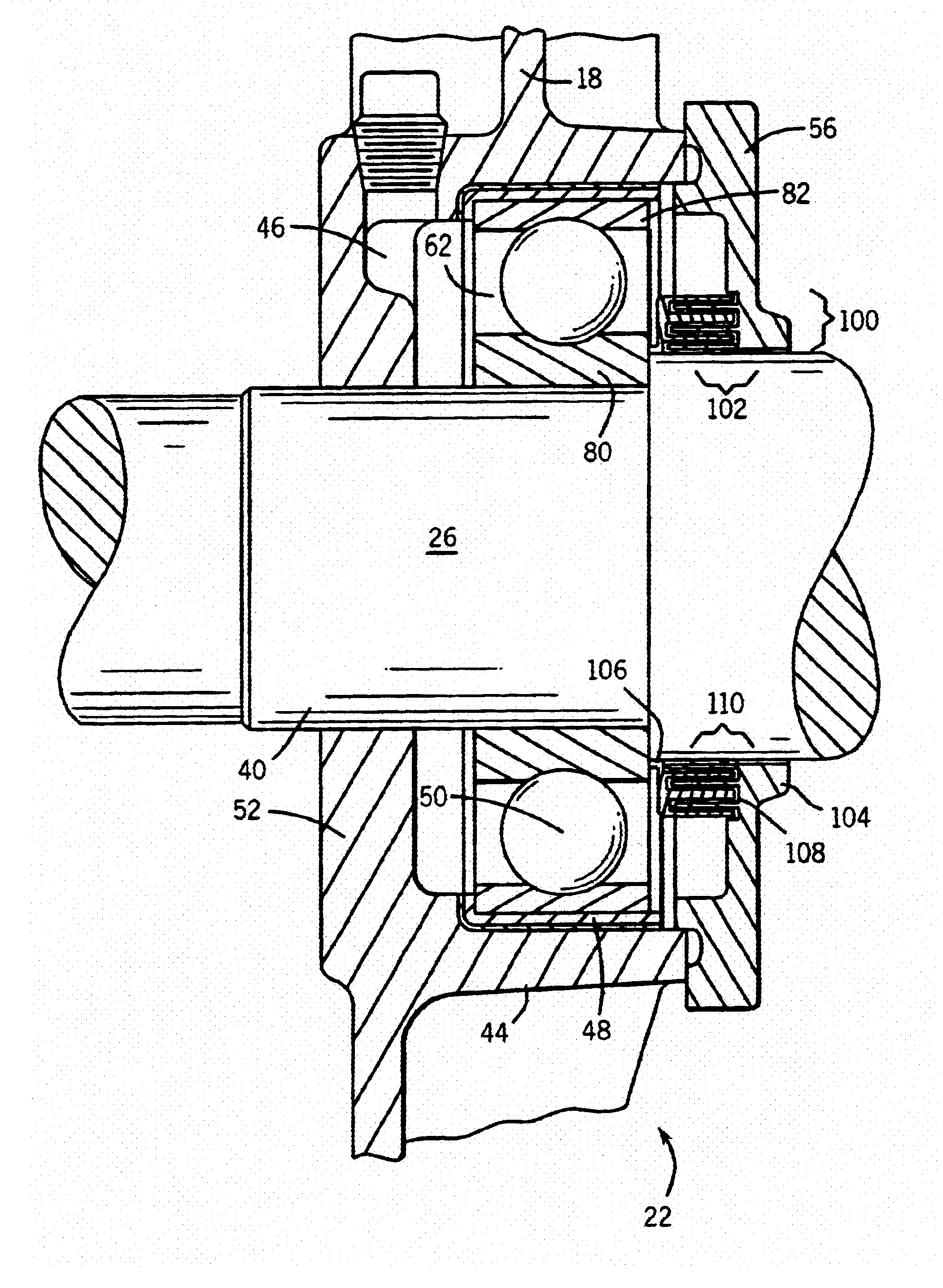
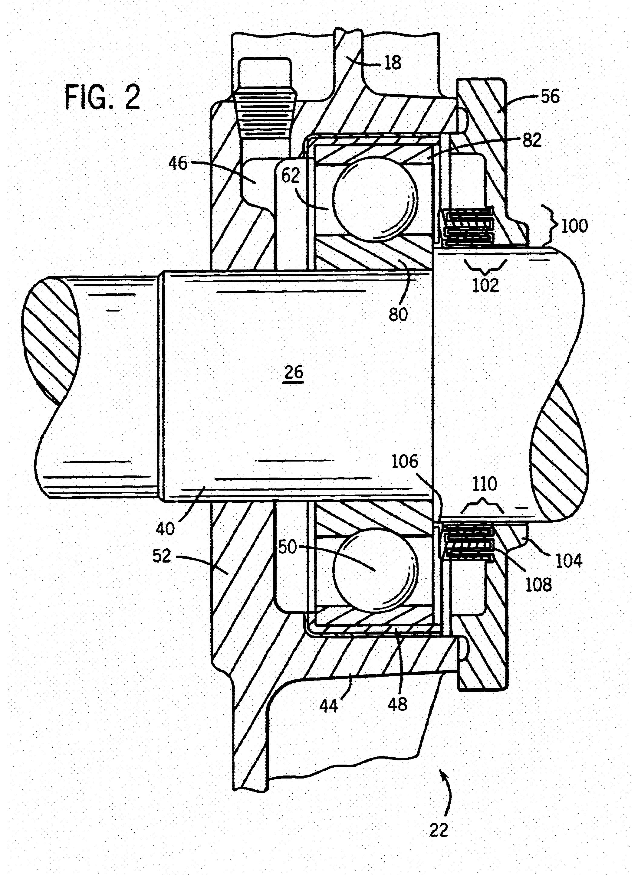
Generally, the present invention relates to reducing the occurrence of V.sub.rg buildup and the resulting EDM events by increasing the C.sub.rf term of the BVR, thereby increasing the denominator of the ratio. This increase in the C.sub.rf term is accomplished, for example, by effectively increasing the surface area closely presented between the rotating assembly and the adjacent grounded surfaces. In this manner shaft surface area inside a motor or other device may be utilized to increase the capacitive surface area by as much as an order of magnitude or more and to thereby decrease the scale of the common mode voltage associated with V.sub.rg in an inverter driven system. By increasing C.sub.rf in this way bearing voltage may be reduced to a non-damaging level.

Further, the gaps created between the rotating assembly and adjacent grounded surfaces may be completely or partially filled with a dielectric material to further increase C.sub.rf. In addition, this dielectric material may ...


PUM


Abstract

Technique for reducing bearing current discharges in a system by increasing the surface area between the shaft and the frame of the system and thereby increasing the rotor to frame capacitance.

Description

1. Field of the InventionThe present invention relates generally to an electromechanical system, such as an electric motor driven by an inverter, and a method for constructing and using the system. The system of the invention is designed to minimize rotor voltage and to thereby minimize bearing voltage and bearing current discharges.2. Description of the Related ArtVirtually all rotating motors, generators, etc. to some degree develop either rotor shaft to ground voltage (V.sub.rg), or shaft end-to-end voltage and resulting bearing currents (I.sub.b). Shaft end-to-end voltage is typically the result of internal electromagnetic induction effects. External sources are a primary cause of V.sub.rg via electrostatic coupling. Modem voltage source inverters, such as pulse width modulation (PWM) inverters, are among those external sources which may be electrostatically coupled and thereby serve as sources of V.sub.rg. The resulting V.sub.rg gives rise to electrostatically induced I.sub.b w...

Claims


Application Information

Patent Timeline
Patent Type & Authority Patents(United States)
IPC IPC(8): H02K11/00
CPCH02K11/0089H02K11/0005H02K11/40H02K11/0141
Inventor MELFI, MICHAEL J.
Owner BALDOR ELECTRIC COMPANY
Why Eureka
Try Eureka