Oil pump

a technology of oil pump and oil pump, which is applied in the direction of liquid fuel engines, rotary/oscillating piston pump components, machines/engines, etc., can solve the problems of reducing the net available horsepower of the engine driving the pump, causing mechanical energy loss to the driving engine in general, and reducing the power of the engin

Inactive Publication Date: 2004-01-20
FEULING JAMES J
View PDF8 Cites 66 Cited by
  • Summary
  • Abstract
  • Description
  • Claims
  • Application Information

AI Technical Summary

Problems solved by technology

Since hydraulic power is a function of flow and pressure, the mechanical energy losses to the driving engine generally are caused by the viscous drag on the gears being driven.
Consequently the gerotor with the smallest outside diameter will generally cause the lowest power loss to an engine driving it due to the developed viscous drag.
Increasing gear size would generally be expected to cause a concurrent decrease in the net available horsepower of the engine driving the pump, since viscous drag is increased from the increased pumping and more horsepower is then required to power the pump.
However, Leppanen teaches the use of a one piece casing housing two adjacent pump gears and fails to teach any benefits derived from the critical ratio of the scavenging gear and resulting pumping volume to the pressure gear and resulting pressure pumping volume.
Troxler teaches the use of a one piece pump housing which is not designed to allow gear ratio adjustments and fails to teach any benefit from such adjustments or increasing the volume pumping size of the pumps.

Method used


Image

  • Oil pump
  • Oil pump
  • Oil pump

Examples


Embodiment Construction

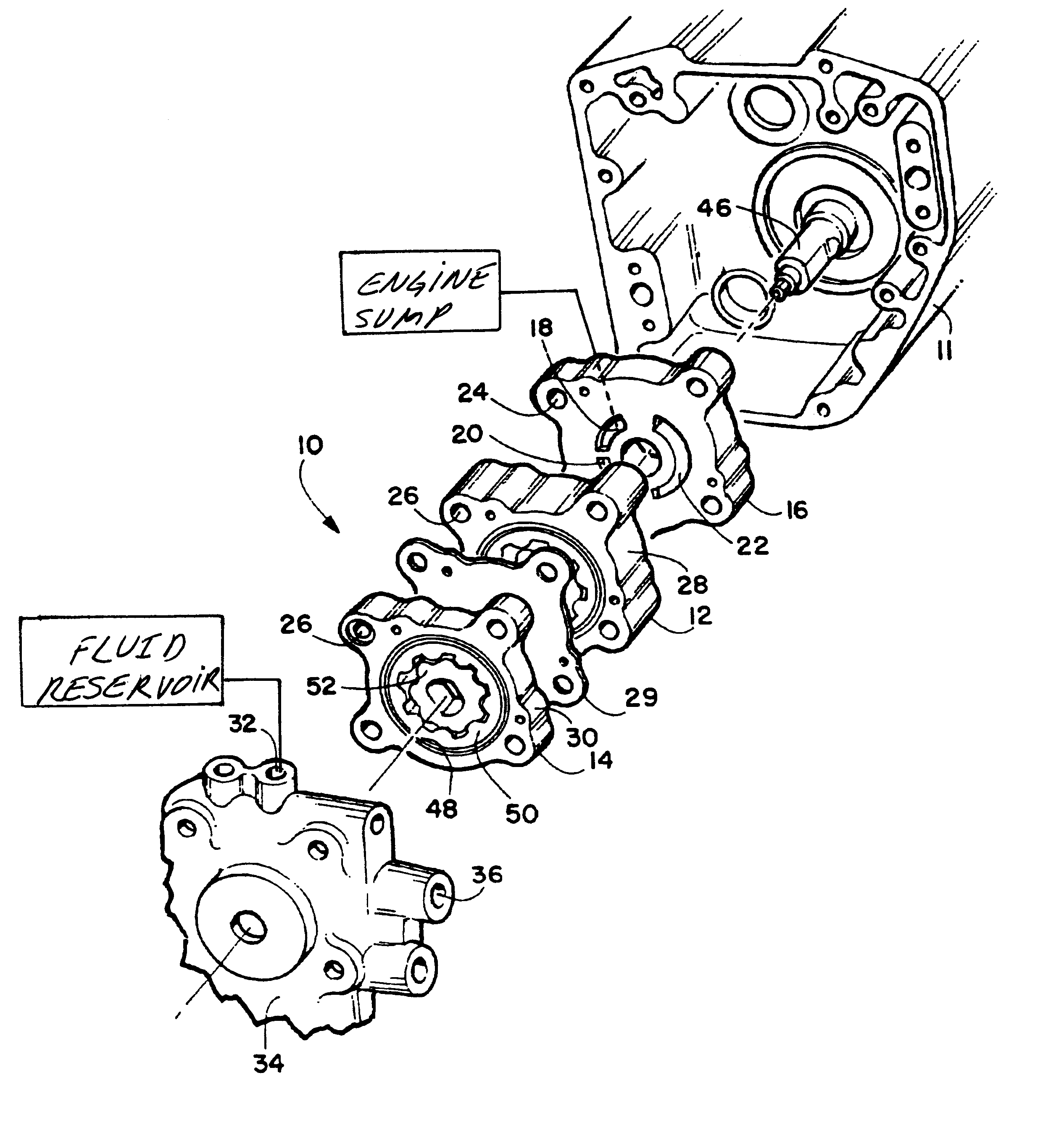
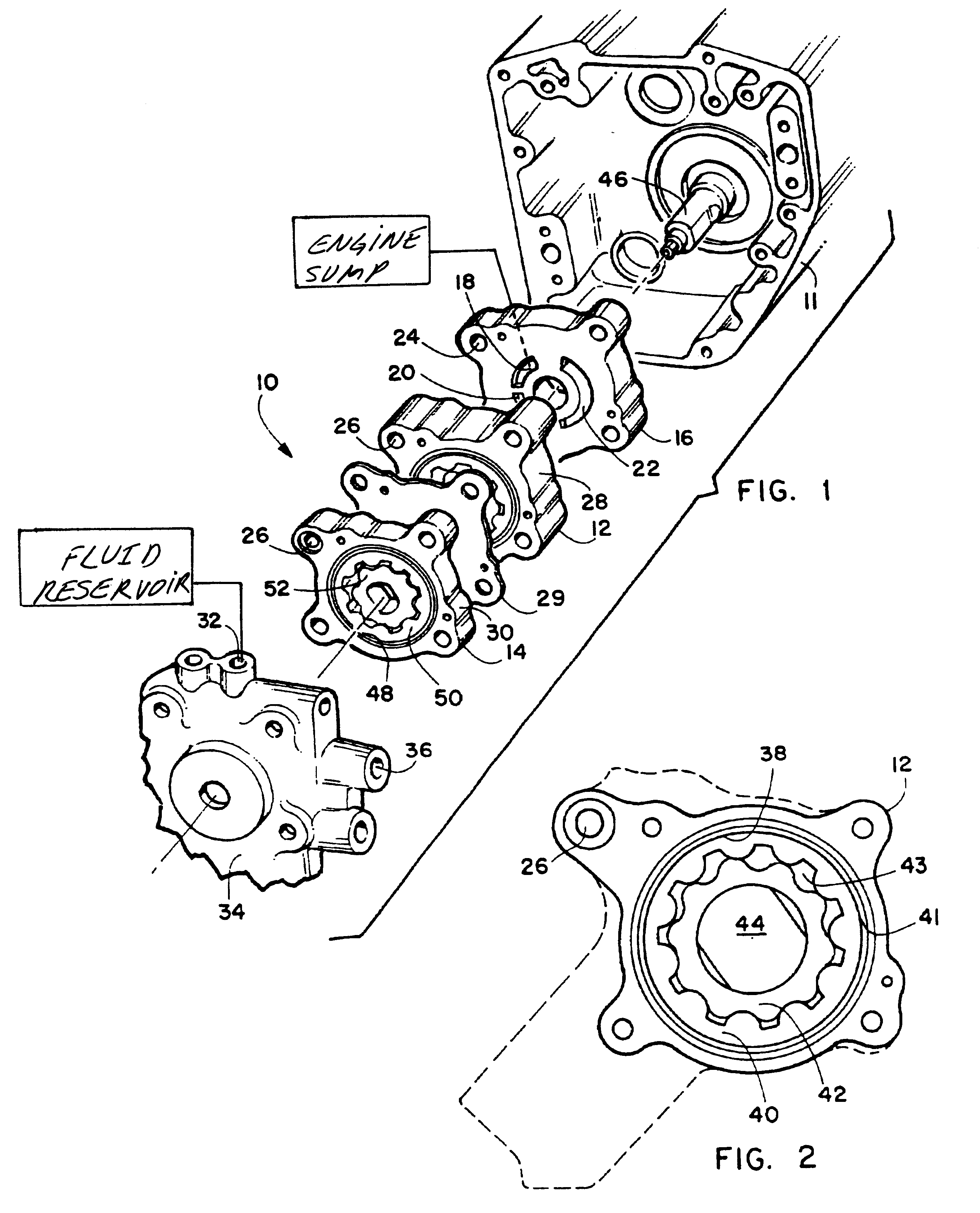
Referring now to the drawings FIGS. 1-4 disclose the preferred embodiments of the herein disclosed device 10 which is a multi chambered oil pump for operative attachment to, and use in combination with, an internal combustion engine 11 such as a motorcycle.

In a first preferred embodiment as shown in FIG. 1 the device 10 features a pair of gerotor pumps to form the device 10 which has a scavenging pump 12 mounted in line with a pressure pump 14. As shown, a pump porting plate 16 provides a means to interface the device 10 with an engine 11 and the oil conduits of the engine and port the lubricating fluid such as oil from one or a plurality of engine sumps (not shown) to one or a plurality of scavenging intake ports, in this case a first savaging intake port 18 and a second scavenging intake port 20 through which oil is drawn into the scavenging pump 12 by negative pressure generated by the scavenging pump 12 at the two intake ports. The two intake ports 18 and 20, would communicate f...


PUM


Abstract

A modular oil pump for use in combination with an internal combustion engine having a dry sump lubrication system. The device features a first gerotor pump having an intake port engageable in communication with at least one engine sump and having an discharge port engageable in sealed communication with a fluid reservoir for the dry sump system. A second gerotor pump, engageable in sealed communication with the fluid reservoir has a discharge port fluidly engageable with the engine lubrication system oil supply conduit. Both the first pump and second pump are assembled from separate housings, and cooperatively engaged inner and outer gears sized for rotation and in line mounting on the engine crankshaft inside a cavity in the housings. The volume pumping capacity of the first pump at a ratio to efficiently drain fluid and gas from the engine sumps and supply the reservoir with a constant supply of lubrication fluid. The device may be assembled from a kit having a plurality of different sized components to adjust the ratio of the pumping volume of the first pump to the second pump.

Description

1. Field of the InventionThe present invention relates to an oil pump for an internal combustion engine. More particularly it relates to an improved gerotor gear oil pump for use with a motorcycle engine employing a dry sump lubrication system and providing an improved design and ratio of scavenging pump capacity to engine supply side capacity. The design provides both improved performance and lubrication for the motorcycle engine and a gain in net horsepower in such an engine despite the use of increased gear size which would normally cause a decrease in net horsepower of the engine. Additionally, the modular design of the preferred embodiment provides the ability to assemble an oil pump with two or more pumping chambers into a single pump unit that is customizable to the required performance characteristics of the motorcycle for the type of riding intended.In a preferred embodiment, the device features a multiple piece formed pump unit having a pressure pump housing and a scavenge...

Claims


Application Information

Patent Timeline
Patent Type & Authority Patents(United States)
IPC IPC(8): F04C11/00F04C13/00F04C2/10F04C2/00
CPCF04C2/102F04C11/001F04C13/00F04C2240/70
Inventor FEULING, JAMES J.
Owner FEULING JAMES J
Why Eureka
Try Eureka