System and method for servoing robots based upon workpieces with fiducial marks using machine vision

a robot and workpiece technology, applied in the field of machine vision systems, can solve the problems of limited servoing approach, unacceptable/defective parts of the surface, and limited servoing approach

Inactive Publication Date: 2004-01-20
COGNEX TECH & INVESTMENT
View PDF17 Cites 333 Cited by
  • Summary
  • Abstract
  • Description
  • Claims
  • Application Information

AI Technical Summary

Problems solved by technology

Where sufficiently serious defects are noted, a part of the surface is marked as unacceptable/defective.
This servoing approach is limited in that it typically only analyzes translational degrees of freedom (e.g. those in the image plane) generally perpendicular to the camera axis, and does not take into account any non-translational degrees of freedom such as

Method used


Image

  • System and method for servoing robots based upon workpieces with fiducial marks using machine vision
  • System and method for servoing robots based upon workpieces with fiducial marks using machine vision
  • System and method for servoing robots based upon workpieces with fiducial marks using machine vision

Examples


Embodiment Construction

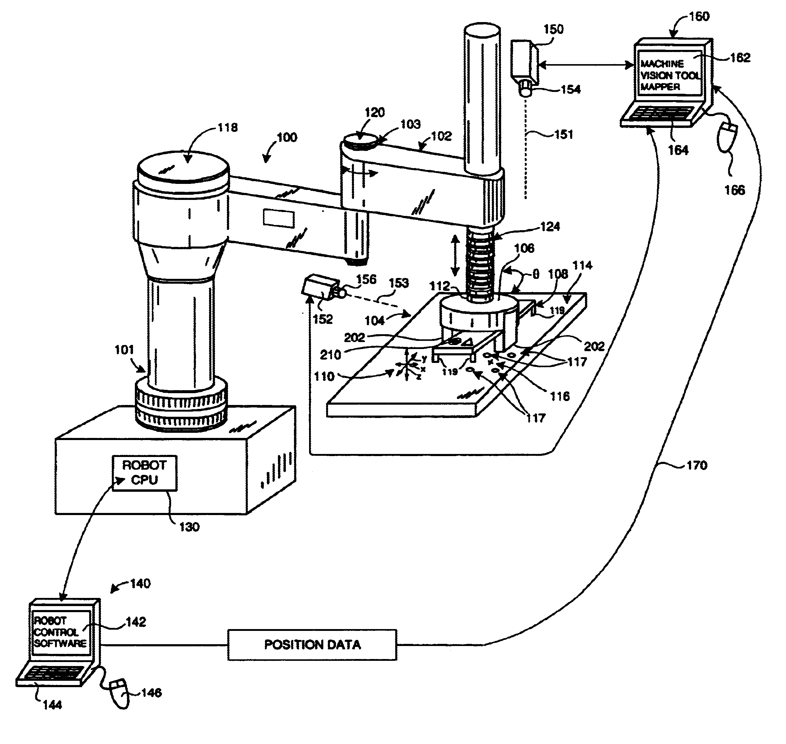
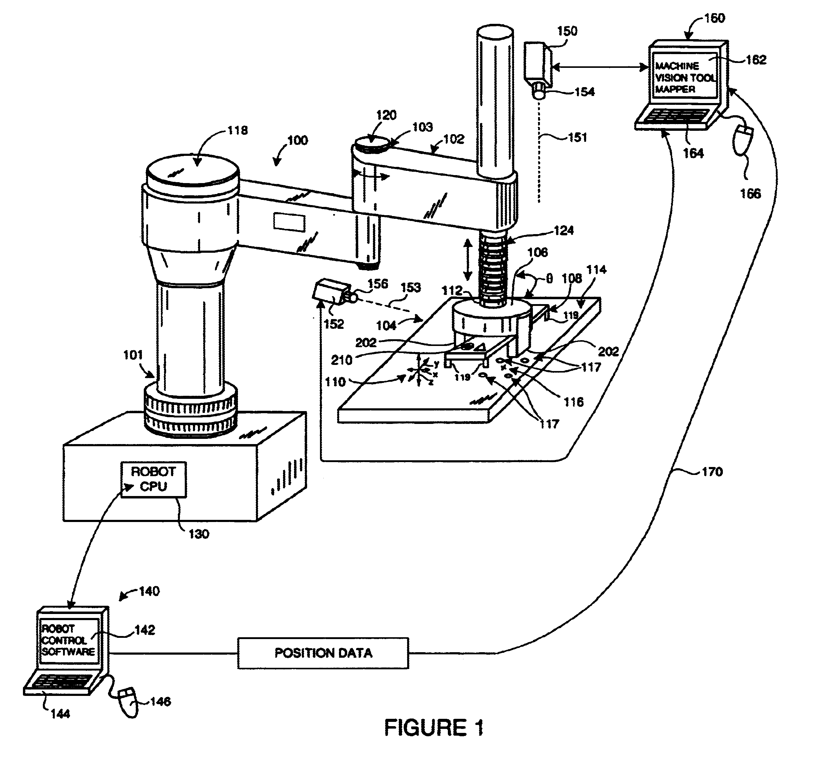
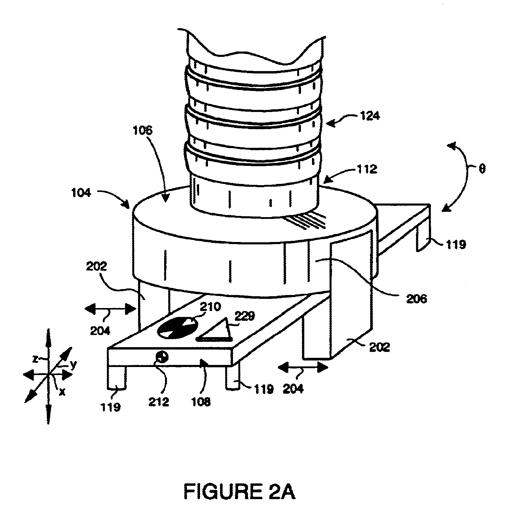
. 1 shows an exemplary robot assembly 100, mounted on a base 101, including a manipulator unit 102 having a multi-jointed arm 103 capable of moving an end effector 104 in at least four degrees of freedom-along three orthogonal axes (axis arrows x, y and z(scale)), and one rotation (curved arrow .theta.). The end effector 104 is provided with a gripper assembly 106 that enables engagement with, and disengagement from, a work-piece 108. The end effector 104 is movable by robot control commands along the three linear axes x, y and z, as shown generally by the set of axis arrows 110. The transverse x and y-axes are typically within the viewed plane perpendicular to the camera axis and an orthogonal z-axis is typically a distance / scale coordinate with respect to the camera. In addition the end effector includes a rotating wrist 112 that enables rotation (curved arrow .theta.) relative to the manipulator arm 103 with the rotation axis generally perpendicular to the plane defined by the x ...


PUM

PropertyMeasurementUnit
Angleaaaaaaaaaa
Angleaaaaaaaaaa
Angleaaaaaaaaaa

Abstract

A system and method for servoing robot marks using fiducial marks and machine vision provides a machine vision system having a machine vision search tool that is adapted to register a pattern, namely a trained fiducial mark, that is transformed by at least two translational degrees and at least one mon-translational degree of freedom. The fiducial is provided to workpiece carried by an end effector of a robot operating within a work area. When the workpiece enters an area of interest within a field of view of a camera of the machine vision system, the fiducial is recognized by the tool based upon a previously trained and calibrated stored image within the tool. The location of the work-piece is derived by the machine vision system based upon the viewed location of the fiducial. The location of the found fiducial is compared with that of a desired location for the fiducial. The desired location can be based upon a standard or desired position of the workpiece. If a difference between location of the found fiducial and the desired location exists, the difference is calculated with respect to each of the translational axes and the rotation. The difference can then be further transformed into robot-based coordinates to the robot controller, and workpiece movement is adjusted based upon the difference. Fiducial location and adjustment continues until the workpiece is located the desired position with minimum error.

Description

1. Field of the InventionThis invention relates to machine vision systems and more particularly to uses for advanced machine vision search tools that register patterns transformed by at least two translational and at least one non-translational degree of freedom.2. Background InformationThe use of advanced machine vision systems and their underlying software is increasingly employed in a variety of manufacturing and quality control processes. Machine vision enables quicker, more accurate and repeatable results to be obtained in the production of both mass-produced and custom products. Basic machine vision systems include one or more cameras (typically having solid-state charge couple device (CCD) imaging elements) directed at an area of interest, frame grabber / image processing elements that capture and transmit CCD images, a computer and display for running the machine vision software application and manipulating the captured images, and appropriate illumination on the area of inter...

Claims


Application Information

Patent Timeline
IPC IPC(8): B25J9/16G05B19/12G05B19/04B25J9/18
CPCB25J9/1697G05B19/128G05B2219/39397G05B2219/40565G05B2219/40607
Inventor WEINZIMMER, RUSSWALLACK, AARON
Owner COGNEX TECH & INVESTMENT
Why Eureka
Try Eureka