Sound barrier layer for insulated heat shield

a technology of insulated heat shield and sound barrier layer, which is applied in the direction of fluid pressure measurement by mechanical elements, vibration measurement in solids, special data processing applications, etc., can solve the problems of insufficient damping of noise, inability to reduce or attenuate noise to satisfactory levels, and significant damage to electronic components sharing under-the-hood space with the manifolds

Inactive Publication Date: 2004-01-27
DANA AUTOMOTIVE SYST GRP LLC
View PDF10 Cites 24 Cited by
  • Summary
  • Abstract
  • Description
  • Claims
  • Application Information

AI Technical Summary

Problems solved by technology

Such high temperatures create significant risks of damage to electronic components sharing under-the-hood space with the manifolds.
One recurrent shortcoming with respect to current shield designs, however, has been in their inability to reduce or attenuate noise down to satisfactory levels.
The insulatio

Method used


Image

  • Sound barrier layer for insulated heat shield
  • Sound barrier layer for insulated heat shield
  • Sound barrier layer for insulated heat shield

Examples


Embodiment Construction

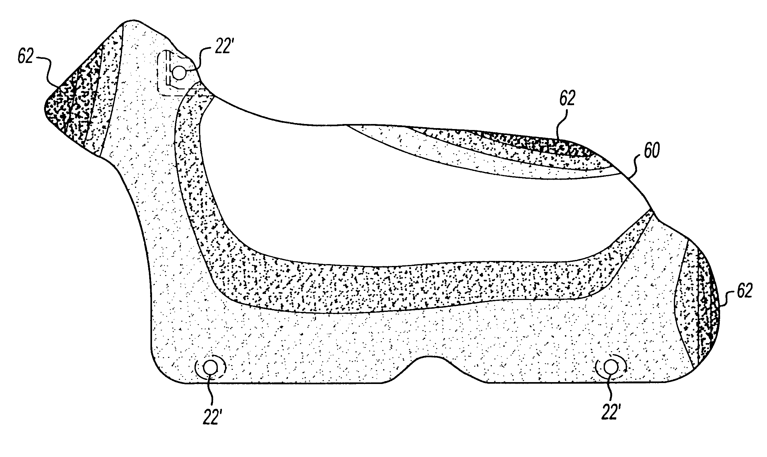
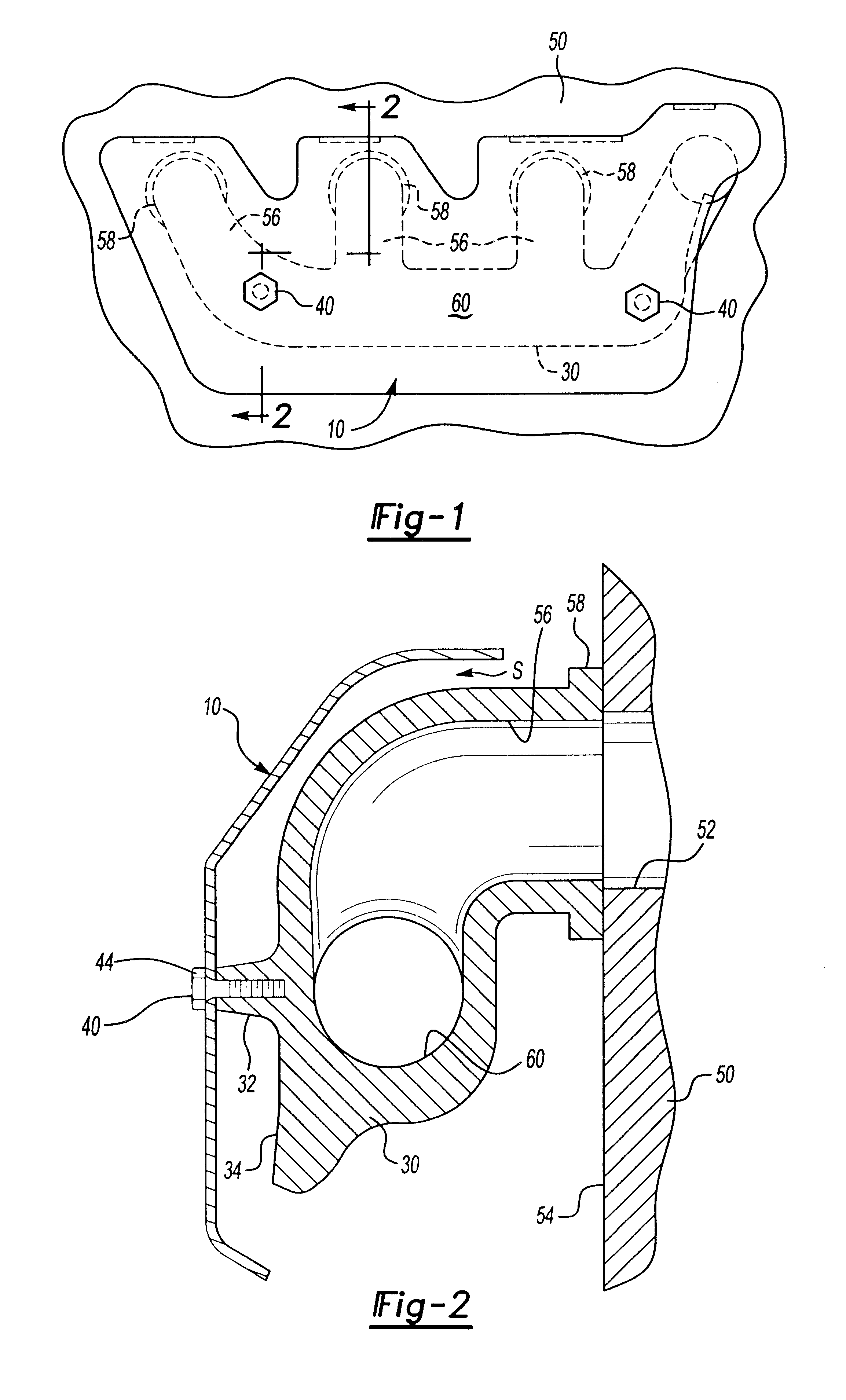
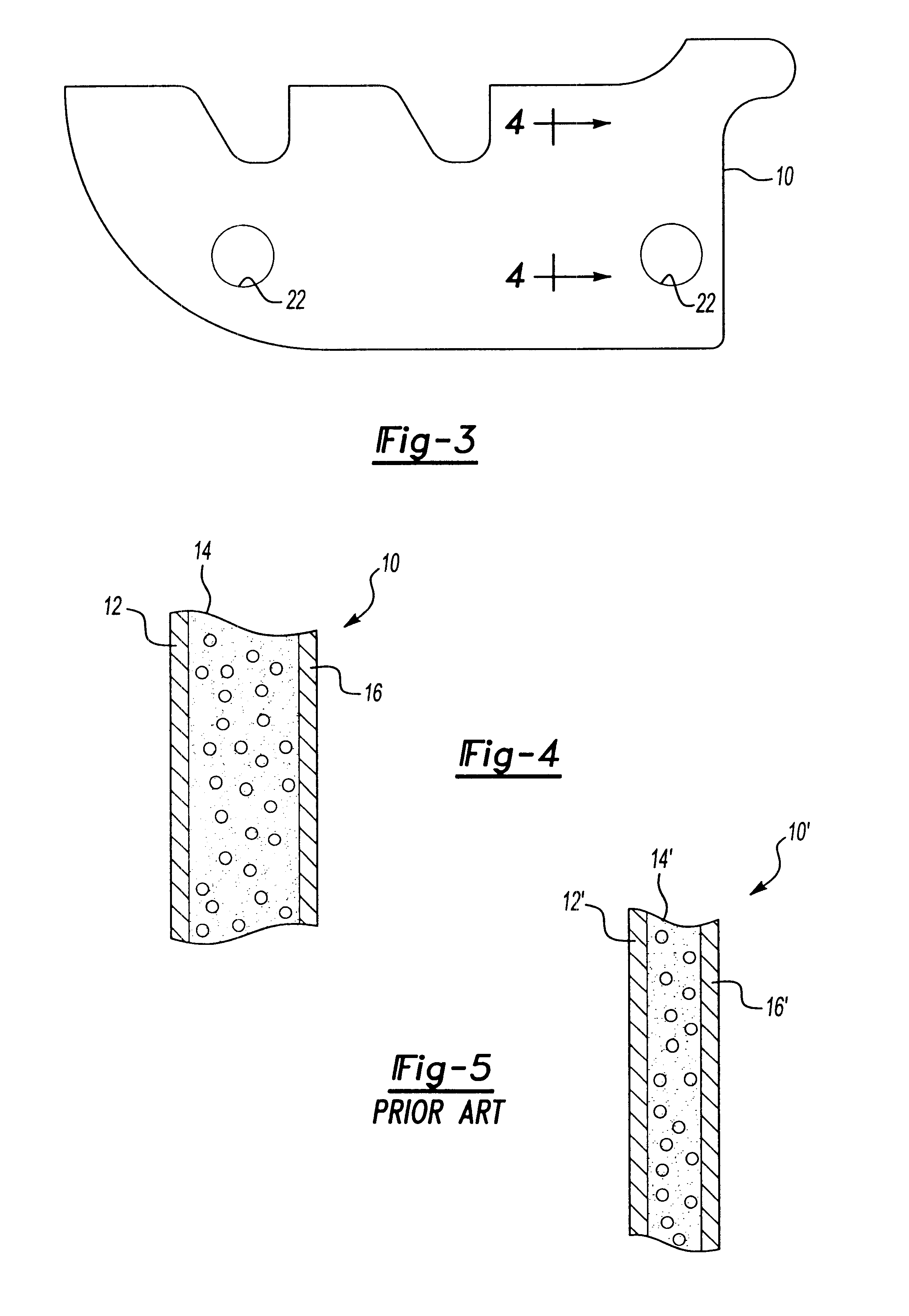
One method of manufacturing a heat shield for an under-the-hood vehicular engine component produces a shield of three layers, including an inner metal layer, an outer metal layer, and a non-metallic insulation layer sandwiched therebetween. The inner metal layer adapted to be positioned directly adjacent or proximal the engine component, and the insulation layer is positioned radially outwardly of the inner metal layer. The layers collectively provide thermal insulation of, and reduced noise transmission from, the engine component. The specific method included the following steps:

a) establishing relative thickness and density values of an insulation layer by using non-linear modal finite element analysis. (For this step, the heat shield is attached to a test component via fastening bolts. The shield is vibrationally excited to measure and map relative amplitudes of vibration over the entire body of the shield.)

b) determining optimal values of the insulation layer thickness and densi...


PUM


Abstract

An improved heat shield provides thermal insulation and reduced noise transmission of vehicular engine components, including exhaust manifolds. The structure has three layers; an outer structural metal layer, a center insulation layer to isolate heat and dampen noise, and an inner metal layer directly adjacent the shielded component for reflecting heat back to the shielded component. The heat shield is attached by bolts to the shielded component. In the described embodiment, the volume of the insulation layer is expanded by approximately 15 to 20 percent over conventional shields to produce a softer, thicker material having a lower density but unchanged mass. The invention provides a technique to achieve desired thickness and density in insulation layers via modal finite element analysis. The relatively thicker heat shield more effectively absorbs vibration and attenuates noise without increase in mass. In the described embodiment, the layer contains cellulose, diatomaceous earth, talc, and fiberglass.

Description

1. Field of InventionThe present invention relates to protective structures for vehicular engine parts, such as for example engine exhaust manifolds that generate substantial heat and vibration during engine operation. More specifically, the invention relates to the fabrication of protective heat shields applied to such engine parts, and particularly for enhancements of insulation layers employed in such shields for reducing transmission of noise and vibration.2. Description of the Prior ArtThe exhaust manifolds of internal combustion engines in today's modern vehicles can reach under-the-hood temperatures in the neighborhood of 1600 degrees Fahrenheit. Such high temperatures create significant risks of damage to electronic components sharing under-the-hood space with the manifolds. Thus, protection has been provided for such components via use of heat shields designed to at least partially cover up and insulate exhaust manifolds and other heat generating components. In some cases, ...

Claims


Application Information

Patent Timeline
IPC IPC(8): F01N7/10F01N7/14F01N13/10F01N13/14
CPCF01N13/102F01N13/14F01N13/10F01N2260/20
Inventor CHEN, COLIN CHING-HOBOOGEMANS, MARKMATIAS, CALIN
Owner DANA AUTOMOTIVE SYST GRP LLC
Why Eureka
Try Eureka