Device for compensating polarization dispersion in an optical transmission system

a technology of optical transmission system and polarization dispersion, which is applied in the direction of optics, optical elements, instruments, etc., can solve the problems of limiting the performance of optical lines, degrading optical signals, and limited performance of optical transmission systems, so as to reduce the fabrication cost of devices

Inactive Publication Date: 2004-02-10
WSOU INVESTMENTS LLC
View PDF8 Cites 8 Cited by
  • Summary
  • Abstract
  • Description
  • Claims
  • Application Information

AI Technical Summary

Benefits of technology

The object of the invention is to reduce the fabrication cost of a device for compensating PMD by exploiting the fact that most digital optical transmission systems apply error detection and correction methods.
wherein the data that is transmitted consists of frames each including redundant data generated by the transmit terminal to enable the receive terminal to detect errors affecting the received frames and said control unit is adapted to minimize the error rate calculated in real time using said redundant data.
However, it should be noted that the possibility of inadequate control when the error rate is very low is not a problem if the code used is an error correcting code, because a small number of errors can normally be corrected. However, even in the case of an error correcting code, it can be beneficial to calculate the error rate from several successive frames, because this enables the algorithm to be provided with an error rate measurement subject to discontinuities of limited amplitude. Moreover, control is kept active to compensate PMD drift as well, which is much slower than the fast fluctuations previously referred to.

Problems solved by technology

The performance of an optical transmission system, in terms of signal quality and bit rate in particular, is limited in particular by the optical properties of the line, which is subject to physical phenomena which degrade the optical signals.
The deformation of the pulses received by the receive terminal can cause errors in decoding the transmitted data and polarization dispersion therefore constitutes a factor limiting the performance of optical lines, whether analogue or digital.
However, the problem remains with "standard" fibers already installed, which have very high polarization dispersions, constituting a major technical obstacle to increasing the transmitted bit rates.
What is more, this problem will also arise for fibers with low polarization dispersion when it becomes necessary to increase the bit rate further.
On the other hand, this solution is costly to implement correctly.
The spectral width of the modulation of the electrical signal is relatively less costly to measure because it is measured only in the electronic part of the receiver, but this parameter does not always correlate with the PMD, which sometimes gives worse results.

Method used


Image

  • Device for compensating polarization dispersion in an optical transmission system
  • Device for compensating polarization dispersion in an optical transmission system
  • Device for compensating polarization dispersion in an optical transmission system

Examples


Embodiment Construction

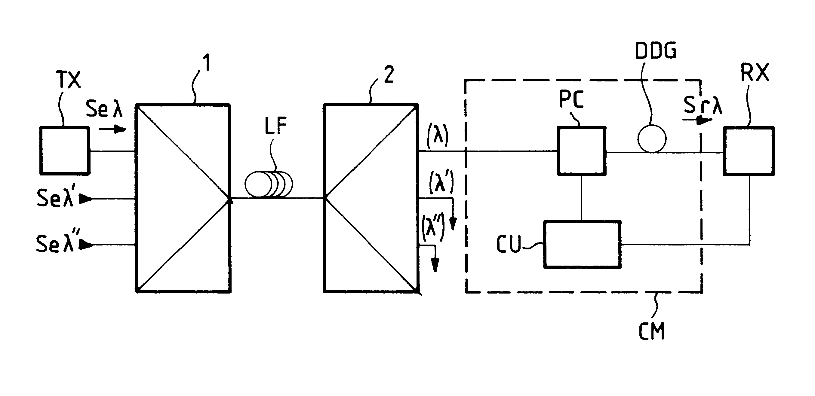
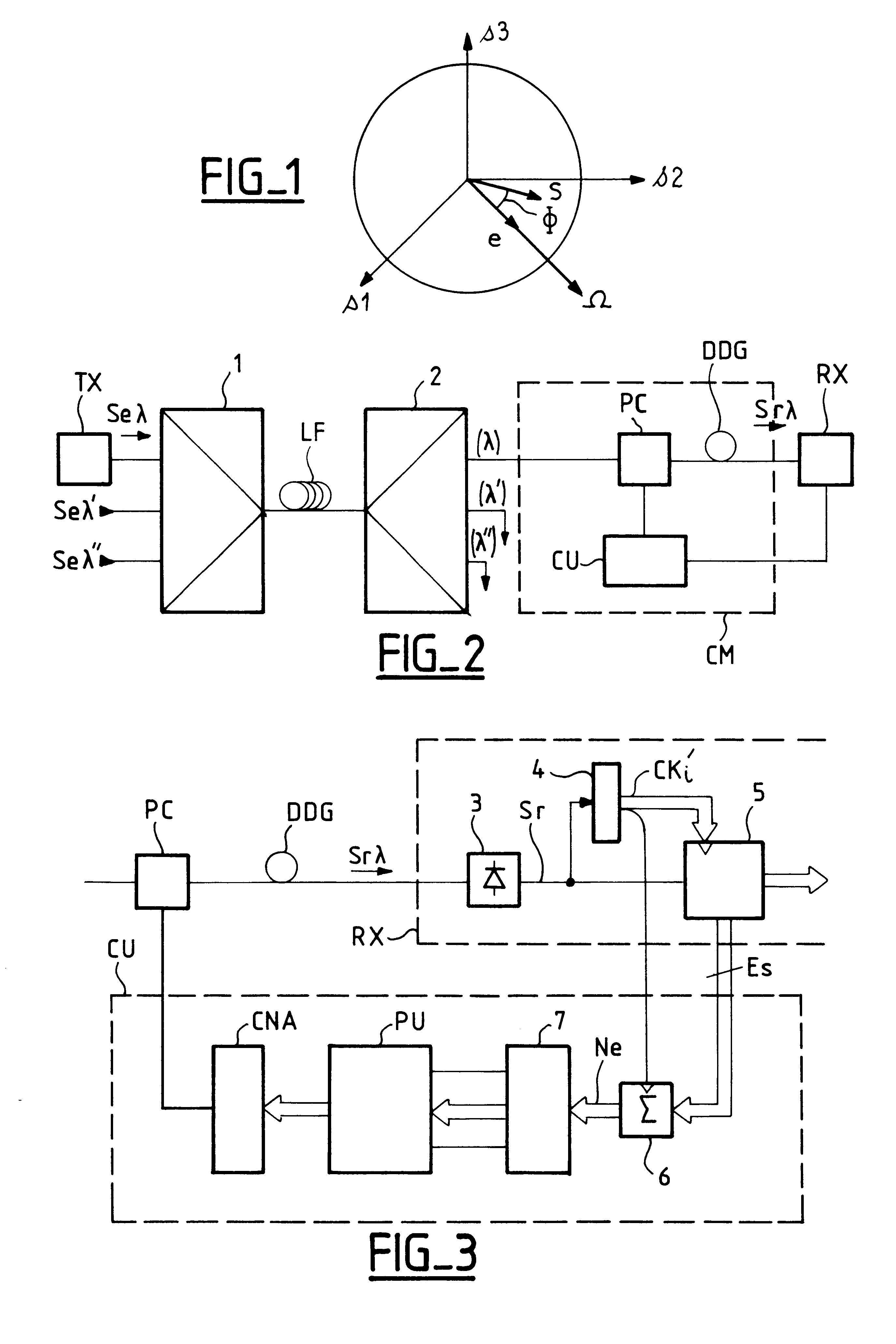
FIG. 2 shows diagrammatically and by way of example an optical transmission system equipped with compensating means according to the invention.

The example shown is a wavelength division multiplex system adapted to convey a plurality of channels Se.lambda., Se.lambda.', Se.lambda." with respective carrier wavelengths .lambda., .lambda.', .lambda.". Each channel, for example the channel Se.lambda., originates from a transmit terminal TX sending an optical signal taking the form of amplitude (and / or optical frequency) modulation of a polarized carrier wave. The channels are combined in a multiplexer 1 whose output is connected to an optical transmission line. That line typically consists of an optical fiber LF and can incorporate optical amplifiers (not shown) at the upstream and / or downstream end of the fiber. The line can equally well consist of a plurality of sections of fiber with optical amplifiers between them.

The end of the line is connected to at least one receiving terminal, f...


PUM


Abstract

The present invention is a device to increase the bit rate and distance at which data can be transmitted by optical fiber. The device compensates the polarization dispersion of the line by processing a received optical signal with the use of a polarization controller, the generation of a differential group delay between two orthogonal polarization modes and a control unit for the polarization controller. The data that is sent is redundant to enable detection of errors affecting the data received and the control unit is adapted to minimize the error rate calculated in real time by using the redundant data. The application of the device is to long-haul optical transmission, in particular over stranded fibers.

Description

The invention relates to the field of optical transmission of digital signals and more particularly transmission at high bit rates on long-haul lines using optical fibers.The invention relates to a device for dynamically compensating at least some of the polarization dispersion that is observed in optical fiber transmission systems.An optical fiber transmission system typically includes:a transmit terminal using at least one optical carrier wave whose power and / or optical frequency it modulates with the data to be transmitted,an optical transmission line consisting of at least one section of monomode fiber conveying the signal sent by the transmit terminal, anda receive terminal receiving the optical signal transmitted by the fiber.The performance of an optical transmission system, in terms of signal quality and bit rate in particular, is limited in particular by the optical properties of the line, which is subject to physical phenomena which degrade the optical signals. Of all the ...

Claims


Application Information

Patent Timeline
Patent Type & Authority Patents(United States)
IPC IPC(8): H04B10/18H04B10/2569
CPCH04B10/2569
Inventor DESTHIEUX, BERTRANDOLLIVIER, FRAN.CEDILLA.OIS-XAVIERPENNINCKX, DENIS
Owner WSOU INVESTMENTS LLC
Why Eureka
Try Eureka