
Cyclocondensed polycyclic hydrocarbon compound and light-emitting device using the same

a technology of cyclocondensed polycyclic hydrocarbons and light-emitting devices, which is applied in the direction of discharge tube luminescnet screens, natural mineral layered products, etc., can solve the problems of blue light-emitting devices that are inferior in luminescence luminance and light-emission efficiency to devices fabricated by vapor deposition, and achieve the effect of increasing light-emission efficiency and decreasing the driving voltage of the devices

Inactive Publication Date: 2004-02-24
UDC IRELAND +1
View PDF8 Cites 9 Cited by
  • Summary
  • Abstract
  • Description
  • Claims
  • Application Information

AI Technical Summary

Benefits of technology

The use of these compounds improves the luminescence properties and durability of blue light-emitting devices, achieving higher luminance and maintaining transparency over time, even when exposed to nitrogen atmospheres.

Problems solved by technology

However, problems have arisen in terms of color purity, durability, luminescence luminance and efficiency, so that it has been desired that these problems should be solved.
However, the devices fabricated by the conventional coating system, in particular, blue light-emitting devices are inferior in luminescence luminance and light-emission efficiency to the devices fabricated by vapor deposition.

Method used


Image

  • Cyclocondensed polycyclic hydrocarbon compound and light-emitting device using the same
  • Cyclocondensed polycyclic hydrocarbon compound and light-emitting device using the same
  • Cyclocondensed polycyclic hydrocarbon compound and light-emitting device using the same

Examples


example 1

A device was prepared in the same manner as with Comparative Example 1 with the exception that compound (1-1) of the invention was used in place of compound A used in Comparative Example 1. The device was evaluated in the same manner as with Comparative Example 1. As a result, blue-green luminescence of (0.19, 0.29) and a maximum luminance of 4280 cd / m.sup.2 were obtained. Even when the device was allowed to stand for one day in an atmosphere of nitrogen, an organic film was transparent.

example 2

A washed ITO substrate was placed in a vapor deposition apparatus, and vapor deposited with .alpha.-NPD (N,N'-diphenyl-N,N'-di (.alpha.-naphthyl)-benzidine) to a thickness of 40 nm. Then, distyryl compound A and compound (1-1) of the invention (distyryl compound A: compound (1-1)=50:1) were concurrently vapor deposited thereon to a thickness of 20 nm, azole compound B was vapor deposited thereon to a thickness of 40 nm, and a cathode was vapor deposited in the same manner as with Comparative Example 1, thereby preparing a device. The device was evaluated in the same manner as with Comparative Example 1. As a result, blue luminescence of (0.16, 0.15) and a maximum luminance of 9600 cd / m.sup.2 were obtained. Even when the device was allowed to stand for one day in an atmosphere of nitrogen, an organic film was transparent.

example 3

Polyvinylcarbazole (40 mg), 12 mg of PBD (p-t-butyl-phenyl-biphenyl-1,2,4-oxadiazole) and 1 mg of compound (1-1) of the invention were dissolved in 3 ml of dichloroethane, and the resulting solution was applied onto a washed substrate by spin coating (2000 rpm, 5 seconds). A cathode was vapor deposited in the same manner as with Comparative Example 1, thereby preparing a device. The device was evaluated in the same manner as with Comparative Example 1. As a result, blue luminescence of (0.15, 0.15) and a maximum luminance of 3180 cd / m.sup.2 were obtained.


PUM

PropertyMeasurementUnit
work functionaaaaaaaaaa
thicknessaaaaaaaaaa
thicknessaaaaaaaaaa

Abstract

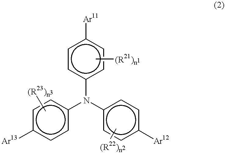
An organic light-emitting device comprising a light-emitting layer or a plurality of organic compound thin layers including a light-emitting layer formed between a pair of electrodes, wherein at least one layer comprises at least one kind of compound represented by the following formula (1):wherein R<11>, R<12 >and R<13 >each represents a group having a cyclocondensed polycyclic hydrocarbon structure in which three or more rings are cyclocondensed; and a novel cyclocondensed polycyclic hydrocarbon compound.

Description

The present invention relates to cyclocondensed polycyclic hydrocarbon compounds, light-emitting device materials which can convert electric energy to light to emit the light, and light-emitting devices. More particularly, the invention relates to light-emitting devices which can be suitably used in the fields of display devices, displays, backlights, electrophotography, illumination light sources, recording light sources, exposure light sources, reading light sources, markings, billboards, interior decorations and the like.At the present time, the research and development of various display devices have been actively made. In particular, organic light-emitting devices have attracted attention as promising display devices, because they can provide highly bright luminescence at low voltage. For example, a light-emitting device in which an organic thin film is formed by vapor deposition of an organic compound (Applied Physics Letters, 51, 913 (1987)) has been known. The light-emitting...

Claims


Application Information

Patent Timeline
Patent Type & Authority Patents(United States)
IPC IPC(8): C07C211/00C07C217/80C07C211/61C07C217/00C07C211/54H01L51/05H01L51/30H01L51/50C09K11/06H05B33/12H05B33/22
CPCC07C211/54C07C211/61C07C217/80H01L51/0058H01L51/0059H01L51/006C07C2103/24C07C2103/26C07C2103/40C07C2103/42C07C2103/48C07C2103/50C07C2103/52C07C2103/54H01L51/0054H01L51/0055H01L51/0056H01L51/5012H01L2251/308Y10S428/917C07C2603/24C07C2603/26C07C2603/40C07C2603/42C07C2603/48C07C2603/50C07C2603/52C07C2603/54H10K85/623H10K85/622H10K85/624H10K85/631H10K85/626H10K85/633H10K50/11H10K2102/103
Inventor IGARASHI, TATSUYA
Owner UDC IRELAND
Learn More