Parallel gas chromatograph with microdetector array

a gas chromatograph and microdetector technology, applied in the field of gas chromatography, can solve the problems of limited interchangeability of components, current state of the art suffers, and relatively bulky packaging

Inactive Publication Date: 2004-03-09
FREESLATE
View PDF61 Cites 78 Cited by
  • Summary
  • Abstract
  • Description
  • Claims
  • Application Information

AI Technical Summary

Benefits of technology

It is therefore an object of the present invention to provide improved gas chromatographs and improved microdetectors for parallel gas chromatography that overcome the deficiencies of the prior art. Specifically, it is an object of the invention to provide a gas chromatograph that is more spatially efficient, provides more operational flexibility, and is more economical to manufacture. It is also an object of the invention to provide gas chromatograph that is suitable for applications with high-throughput screening (e.g. of catalysts), including screening of catalysts using parallel flow reactors or parallel flow microreactors.
The parallel detection systems disclosed herein, comprising a microdetector array, overcome the substantial cost and space constraints of conventional gas chromatographs. The gas chromatographs of the present invention also offer significant improvements with respect to modularity and interchangeability of components, and especially of the detectors. Significantly, the microfabricated microdetectors can be economically manufactured using conventional microfabrication techniques, allowing for improved manufacturing approaches. Microfabrication also provides reproducible, advantageous performance characteristics, especially when applied in connection with forming thin-film detection filaments. The detection systems disclosed herein also provide improvements in sample-handling efficiency and, as such, improve overall sample throughput for a catalysis research program.
The gas chromatography columns 510 are preferably enclosed in a heated environment (e.g., oven), with temperature control capabilities ranging, without limitation from about -10.degree. C. to about 400.degree. C., more typically from about room temperature to about 400.degree. C., and often from about 40.degree. C. to about 400.degree. C. Conventional ovens can be readily employed with most embodiments of the invention. Preferably, however, the heated environment is adapted as described herein to provide significantly improved thermal control, as compared to conventional ovens, for systems having larger numbers (e.g. eight or more as described below) of gas chromatography columns. More specifically, the heated environment is adapted to provide a substantially (temporally) uniform temperature profile as compared between the eight or more columns. For example, the temperature of each of the eight or more columns--taken at substantially the same spatial location on each column at a given time during a temperature excursion of at least about 10.degree. C.--preferably varies by not more than about 5.degree. C., more preferably by not more than about 2.degree. C., even more preferably by not more than about 1.degree. C., still more preferably by not more than about 0.5.degree. C., and most preferably by not more than about 0.1.degree. C. Additionally, in some embodiments, the time-rate-of-change in temperature of the eight or more gas chromatography columns--measured at substantially the same spatial location on each column at a given time during a temperature excursion of at least about 10.degree. C.--preferably varies by not more than about 10%, preferably by not more than about 5%, more preferably by not more than about 2%, still more preferably by not more than about 1%, and most preferably by not more than about 0.5%. The thermal profiles are preferably substantially consistent between columns (as specifically and variously characterized above) during a temperature excursion of at least 20.degree. C., and more preferably of at least about 50.degree. C.
Advantageously, thin-film detection filaments can be designed with a variety of surface geometries and a corresponding variety of associated surface areas for contact with the gaseous sample. As non-limiting examples, the thin-film detection filament can include a serpentine design, a zig-zag design, or a square-point meandering design, among others, on a support of the same design or on substantially planar support. Thin-film detection filaments can also be made with a substantial variety of materials elements and compounds or alloys, to provide various detection attributes, depending on the application of interest. As such, the substantial design flexibility offered in connection with thin-film detection filaments provides a fundamental advantage over conventional, thermistor-based (e.g., bulk wire type) detection filaments. Significantly, higher sensitivities can be achieved as compared to most conventional TCD's by optimizing the heat-transfer characteristics associated with the bridge support structure.
The particular design of the thermal conductivity detector is not narrowly critical. In particular, any thermal conductivity detector design suitable for detection of a gaseous component can be used in connection with the present invention, and the particular design features discussed herein are to be considered exemplary unless expressly recited in the claims. With reference to FIGS. 5A through 5D, for example, the orientation of the inlet port 512 and the outlet port 514 to the detection cavity 516 can vary. The inlet port 512 and outlet port 514 can each be directionally aligned with the axial dimension and flowpath of the detection cavity 516 (FIG. 5A), or can be directionally normal thereto (FIGS. 5B through 5D). Likewise, the particular orientation of the detection filament 520 relative to the detection cavity is not critical to the invention. As shown, for example, the detection filament (and corresponding support for a thin-film detection filament) can be suspended across the axial dimension and flowpath of the detection cavity at an angle (e.g. at a non-normal angle, .theta. (FIGS. 5A and 5B), or at a normal angle (FIG. 5C)). The detection filament 520 can also be suspended in the detection cavity 516 directionally aligned with the axial dimension and flowpath of the detection cavity (FIG. 5D). Moreover, a thermal conductivity detector can include more than one detection filament 520 in the detection cavity 516. In some cases, multiple detection filaments can be used to improve the design characteristics of the thermal conductivity detector. In some applications, multiple detection filaments can be used to effect combined, multifunctional detectors, such as a combined thermal conductivity detector and anemometer. The detection filament can comprise or consist essentially of any material (e.g., element, compound (including polymeric materials) or alloy) that has a temperature-dependent resistance. Platinum and mixed-metal oxides, typically transition metal oxides such as tin oxide, gallium oxide, etc. are preferred detection filament materials.
Advantageously, in one embodiment for providing flow to and from the microdetector, the first and second apertures 512', 514' of the bottom laminate 620 are sized to correspond to the outside diameter of a pair of capillaries--specifically a first inlet capillary 642 (e.g. in fluid communication with a gas chromatography column) and a second outlet capillary 644. The inlet capillary 642 and outlet capillary 644 can each be bonded (e.g. with a high-temperature glue such as an epoxy or polyimide, or anodically bonded or fusion bonded) to the first and second apertures 512', 514' of the bottom laminate 620, to create a macro-scale to micro-scale flow transition having substantially minimal, if any, dead volume. The bottom laminate 620 serves to support, as well as align the external capillaries 642, 644 to the inlet and outlet ports 612, 614, respectively, of the filament laminate 610.

Problems solved by technology

In particular, the current state of the art suffers from relatively bulky packaging, limited interchangeability of component parts, limited operational flexibilty and considerable manufacturing expense.
Moreover, existing gas chromatographs are not readily integrated into reaction systems, and especially into smaller-scale reactors such as microreactors, for catalyst screening and / or process optimization.

Method used


Image

  • Parallel gas chromatograph with microdetector array
  • Parallel gas chromatograph with microdetector array
  • Parallel gas chromatograph with microdetector array

Examples


example 1

Microfabrication of Integral Thermal Conductivity Detector

An array comprising microfabricated thermal conductivity detectors was made using substantially known prior art microfabrication techniques. Briefly, with reference to FIGS. 6A through 6P (and where indicated, also to FIGS. 5L and 5M), fabrication was effected as follows:

1. Wafer 1 (bottom capillary wafer 620 (FIG. 5L), 400 .mu.m thick), and Water 2 (central filament wafer 610 (FIGS. 5L and 5M) 400 .mu.m thick) were provided. Both Wafer 1 and Wafer 2 were single-crystal silicon wafers (Si-wafers): oriented; 125 mm diameter; 400 .mu.m thickness; and double-sided polished.

2. Wafer 1 was oxidized on both sides (oven at 1100.degree. C., wet, about 3.3 .mu.m thick).

3. Wafer 1: spinning of photo resist on front side / baking.

4. Wafer 1: spinning of photo resist on back side / baking.

5. Wafer 1: double-sided photolithography (1) on front side of wafer (fluidic holes for inlet port and outlet port, 150 .mu.m diameter) and back side of w...

example 2

Microfabrication of Integral Thermal Conductivity Detector

In an alternative embodiment, an array comprising microfabricated thermal conductivity detectors was made using substantially known prior art microfabrication techniques. Briefly, with reference to FIGS. 10A through 10E, (and where indicated, also to FIGS. 7F and 7G), fabrication was effected as follows:

1. A wafer (filament wafer 680 (FIGS. 7F and 7G), 400 .mu.m thick) was provided. The wafer was single-crystal silicon: oriented; 125 mm diameter; 400 .mu.m thickness; and double-sided polished.

2. A SiN layer was deposited on both sides (LPCVD, 1 .mu.m thickness) (See FIG. 10A).

3. The top side of the filament wafer 680 was subseqently patterned, and the filament 520 and contact pads 523, 524 were formed as Cr / Pt layers, substantially as described in Example 1. (See FIG. 10B).

4. Both sides of the SiN were then patterned (using photolithography and etching) in preparation for formation of the detection cavity lower portion 516b ...

example 3

Analysis of Liquid Samples

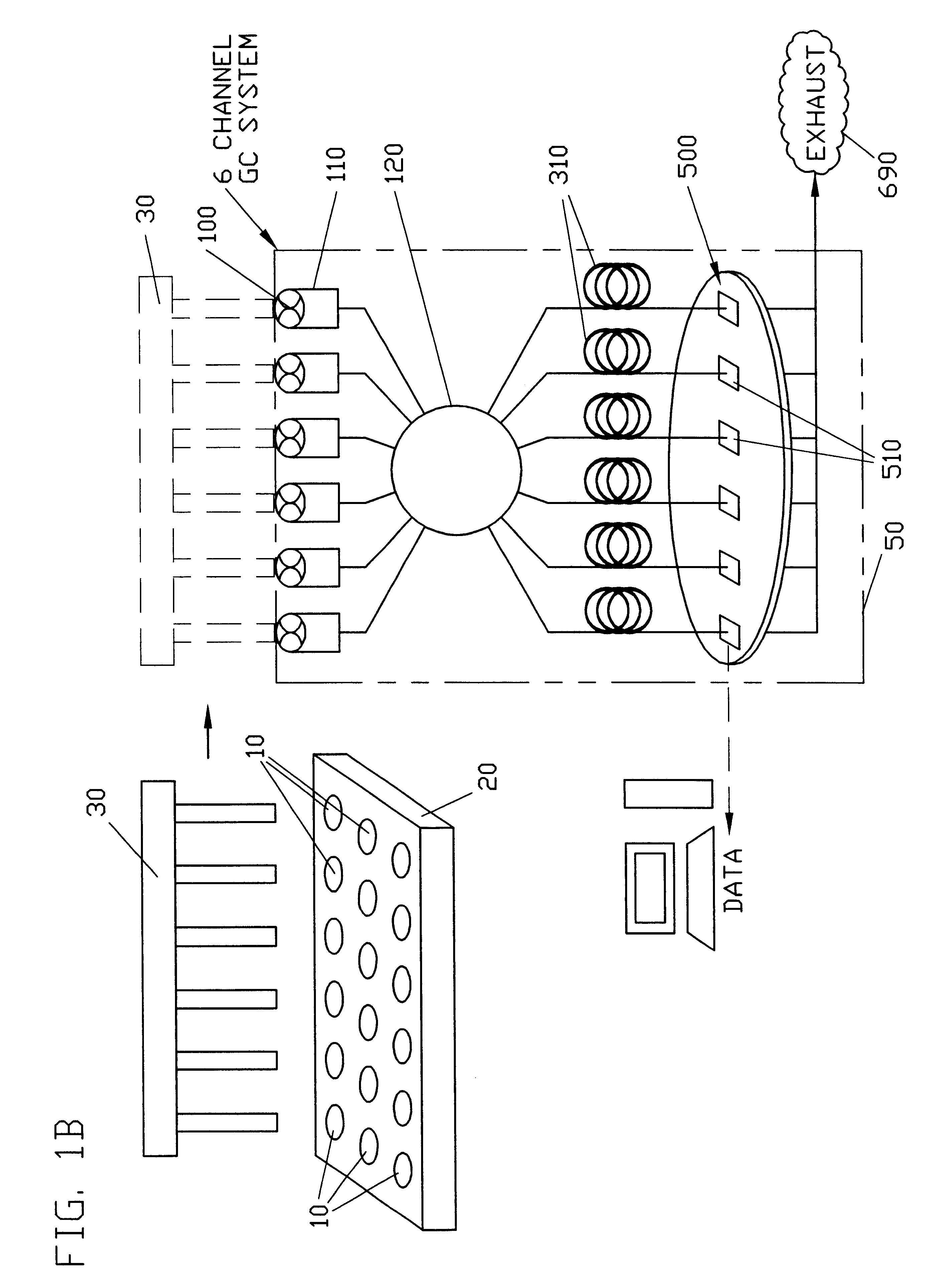
A six-channel gas chromatograph instrument comprising an array of microdetctors as disclosed herein was used to screen a 96-sample microtiter plate using a 1% decane in benzene mixture in every well of the plate. The results of the chromatogram for six channels of a single run are shown in FIG. 9. The nitrogen peak is the residual purge gas present in the injection block and does not interfere with the chromatogram. Conventional gas chromatograms (GC's) use helium as the purge gas, which cannot be distinguished from the carrier gas which is also helium. The nitrogen peak in the parallel GC offers the ability to monitor for mis-injections. The nitrogen peak is typically very large in case of a bad injection (not shown in FIG. 9). The variation in peak area from run to run (after calibration) is less than 10%. The total run-time for the 96 samples was .about.58 minutes total, which is less than a factor of six compared with what would have been required using...


PUM

PropertyMeasurementUnit
volumeaaaaaaaaaa
volumeaaaaaaaaaa
volumeaaaaaaaaaa

Abstract

Gas chromatographs of the invention generally comprise four or more analysis channels. Specifically, four or more gas chromatography columns are configured for parallel analysis of four or more gaseous samples with detection being effected using a microdetector array comprising four or more microdetectors. In one embodiment, the four or more microdetectors 510 are microfabricated detectors, and are integrally formed with a substrate or with one or more microchip bodies mounted on a substrate. In a preferred embodiment, a microdetector array comprises four or more thermal conductivity detectors having one or more thin-film detection filaments. A preferred heated environment for highly parallel gas chromatographs is also disclosed.

Description

BACKGROUND OF INVENTIONThe present invention generally relates to gas chromatography, and specifically, to parallel gas chromatograph systems that can be integrated or used with parallel reactors for high-throughput (i.e., combinatorial) catalyst screening. The present invention also generally relates to microdetectors, and specifically, to microfabricated thermal conductivity detectors suitable for use in gas chromatography, flow detection, catalyst characterization, and other applications. The invention particularly relates, in a preferred embodiment, to parallel gas chromatograph systems with an array of microdetectors, such as microfabricated thermal conductivity detectors.Gas chromatography, and in particular, multi-channel gas chromatography is known in the art. See, for example, PCT patent application WO 00 / 23734 (Daniel Industries, Inc.). Thermal conductivity detectors are also known in the art, and have been routinely used for detection in gas chromatographs--alone, or in c...

Claims


Application Information

Patent Timeline
Patent Type & Authority Patents(United States)
IPC IPC(8): B01J19/00G01N30/66G01N30/00G01N30/18G01N30/86G01N30/30G01N30/46G01N30/60G01N30/88
CPCB01J19/0046G01N30/18G01N30/66B01J2219/00286B01J2219/00306B01J2219/00704G01N30/466G01N30/6004G01N30/6095G01N30/8631G01N2030/185G01N2030/208G01N2030/3084G01N2030/8881
Inventor SRINIVASAN, RAVIPINKAS, DANIEL MERONGUAN, SHENHENGMYSLOVATY, MICHAELSPITKOVSKY, MICHAELENGSTROM, JAMES R.BERGH, H. SAM
Owner FREESLATE
Why Eureka
Try Eureka