Exhaust emission control device

a technology of emission control device and exhaust pipe, which is applied in the direction of electrical control, exhaust treatment electric control, separation process, etc., can solve the problems of engine output decline, dpf melting away, and soot not fully removed

Inactive Publication Date: 2004-03-23
MITSUBISHI MOTORS CORP
View PDF20 Cites 85 Cited by
  • Summary
  • Abstract
  • Description
  • Claims
  • Application Information

AI Technical Summary

Benefits of technology

Herein, when the first and second determination conditions are established at the same time, and if the temperature sensed by the temperature sensing means is higher than or equal to the predetermined temperature that is lower than the temperature to enhance the conversion efficiency of the catalyst into NO.sub.2, the control means activates the regeneration assist means, because there is a small difference between the exhaust gas temperature or the temperature of the catalyst and the temperature to enhance the conversion efficiency of the catalyst into NO.sub.2. Thereby, it takes a shorter time to control (elevate) the temperature, and it is possible to continuously regenerate the particulates owing to catalytic action of the catalyst, with reduced consumption energy.
Namely, even in the state where the first determination condition is established, the suction air amount is restricted because the suction throttle or exhaust throttle is controlled on the closed valve side in the decelerating state, whereby the exhaust gas temperature is prevented from falling, the conversion of the catalyst into NO2 is sufficiently made, and the combustion of particulates deposited on the filter by NO2 is promoted. Therefore, it is possible to prevent the wasteful energy consumption by inhibiting the control (temperature elevation activation) for the exhaust gas temperature or the temperature of the catalyst by the regeneration assist means in the decelerating state.

Problems solved by technology

Since this oxidizing ability typically depends on the temperature of the exhaust gas surrounding the oxidation catalyst, the soot is not fully removed and the residual soot is accumulated on the DPF when the exhaust gas temperature is below a predetermined temperature that is required for the soot combustion.
If the soot is excessively deposited on the DPF, there is a risk that the engine output is decreased and also the DPF melts away due to abnormally high temperatures during the soot combustion.
However, this method is inferior in the fuel consumption because excess fuel is consumed, and must be improved for the practical use.
However, with this method, since a variation in the exhaust gas temperature is gentle, it takes a long time to elevate the temperature, greatly aggravating the fuel consumption, when the exhaust gas temperature greatly falls below the maximum conversion temperature range.
Also, the control means activates the regeneration assist means if the temperature sensed by the temperature sensing means is below the predetermined temperature that is lower than the temperature to enhance the conversion efficiency of the catalyst into NO.sub.2, there is a large difference between the exhaust gas temperature or the temperature of the catalyst and the temperature to enhance the conversion efficiency of the catalyst into NO.sub.2, in which it takes a longer time to control (elevate) the temperature, with increased consumption energy.

Method used


Image

  • Exhaust emission control device
  • Exhaust emission control device
  • Exhaust emission control device

Examples


Embodiment Construction

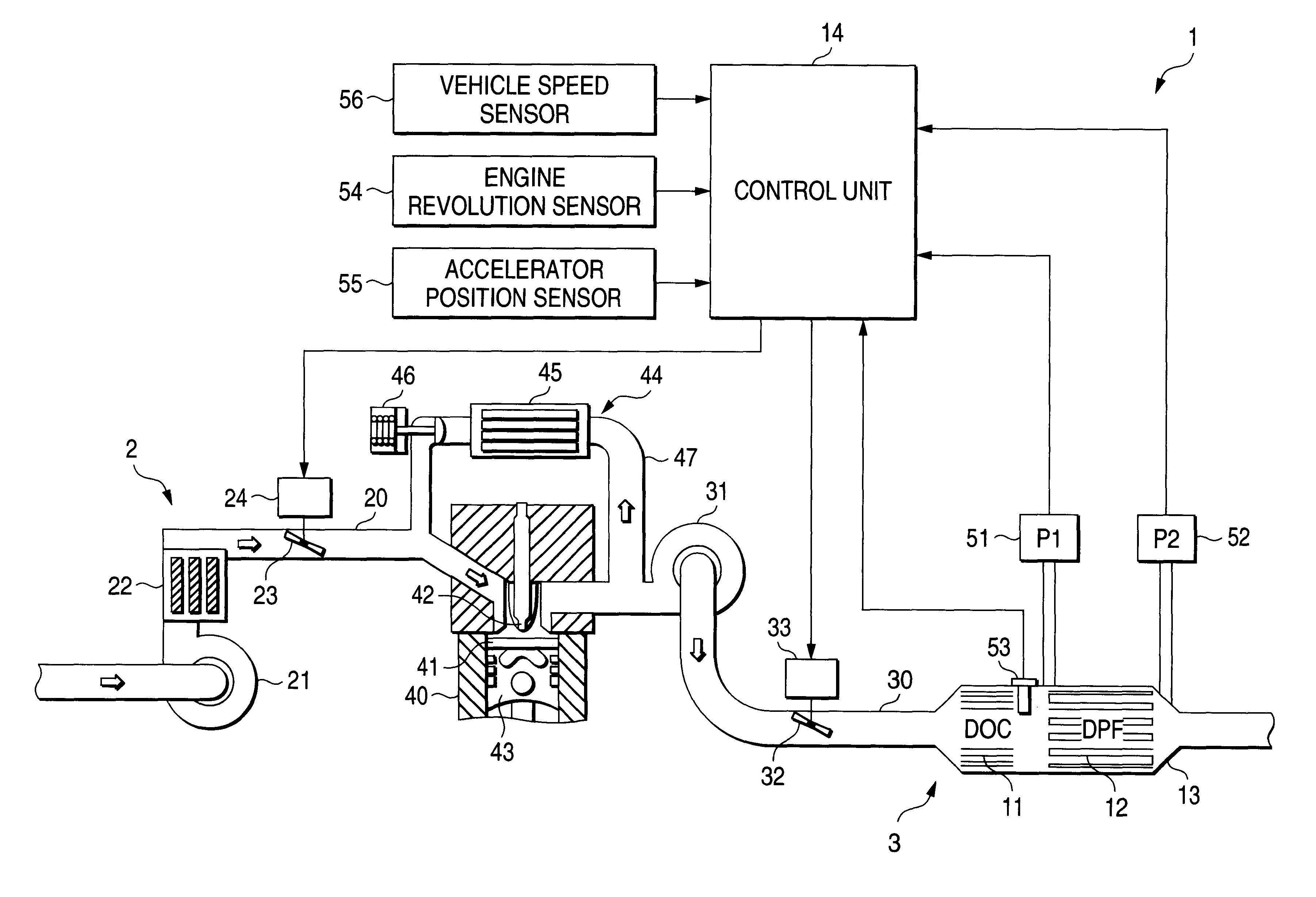
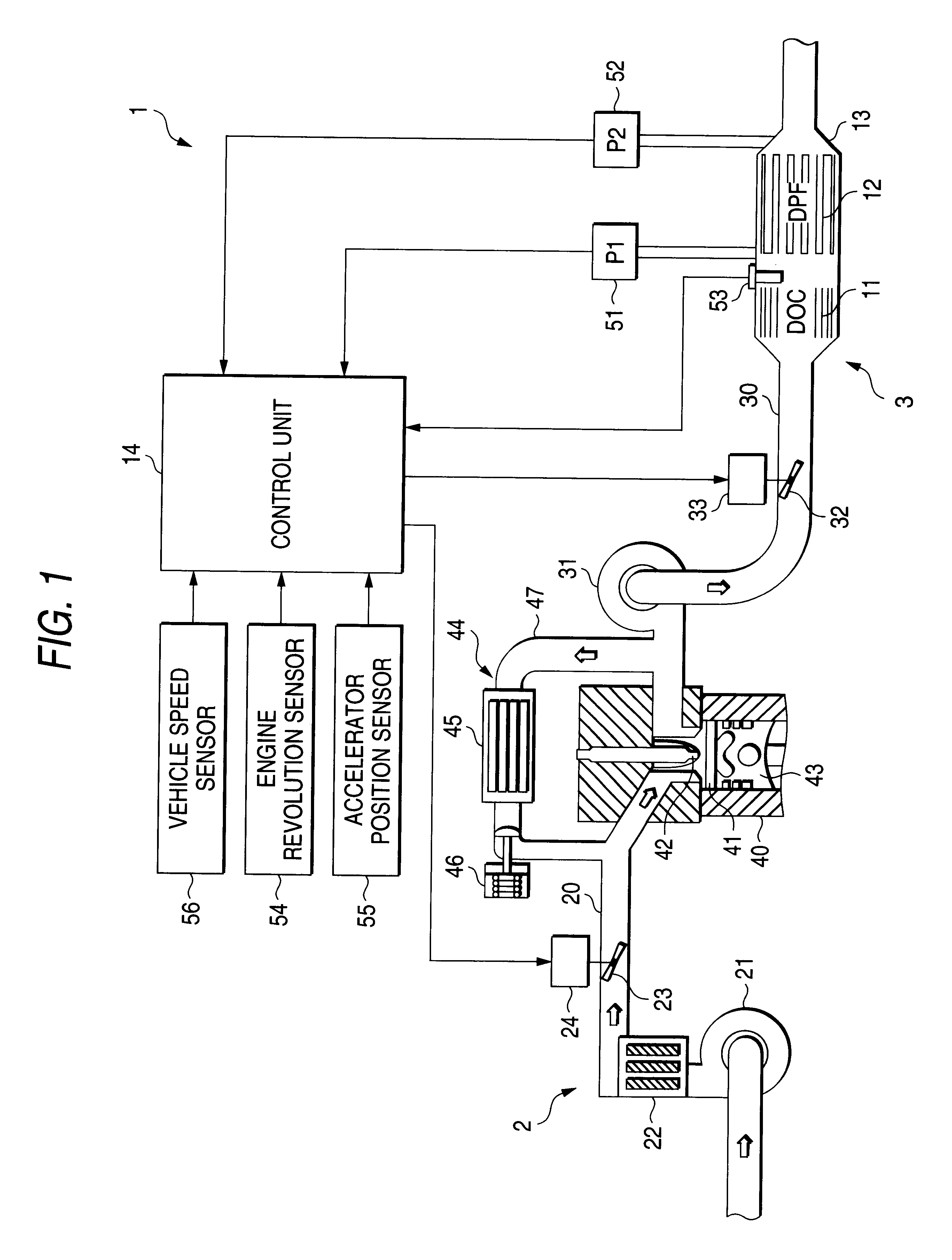
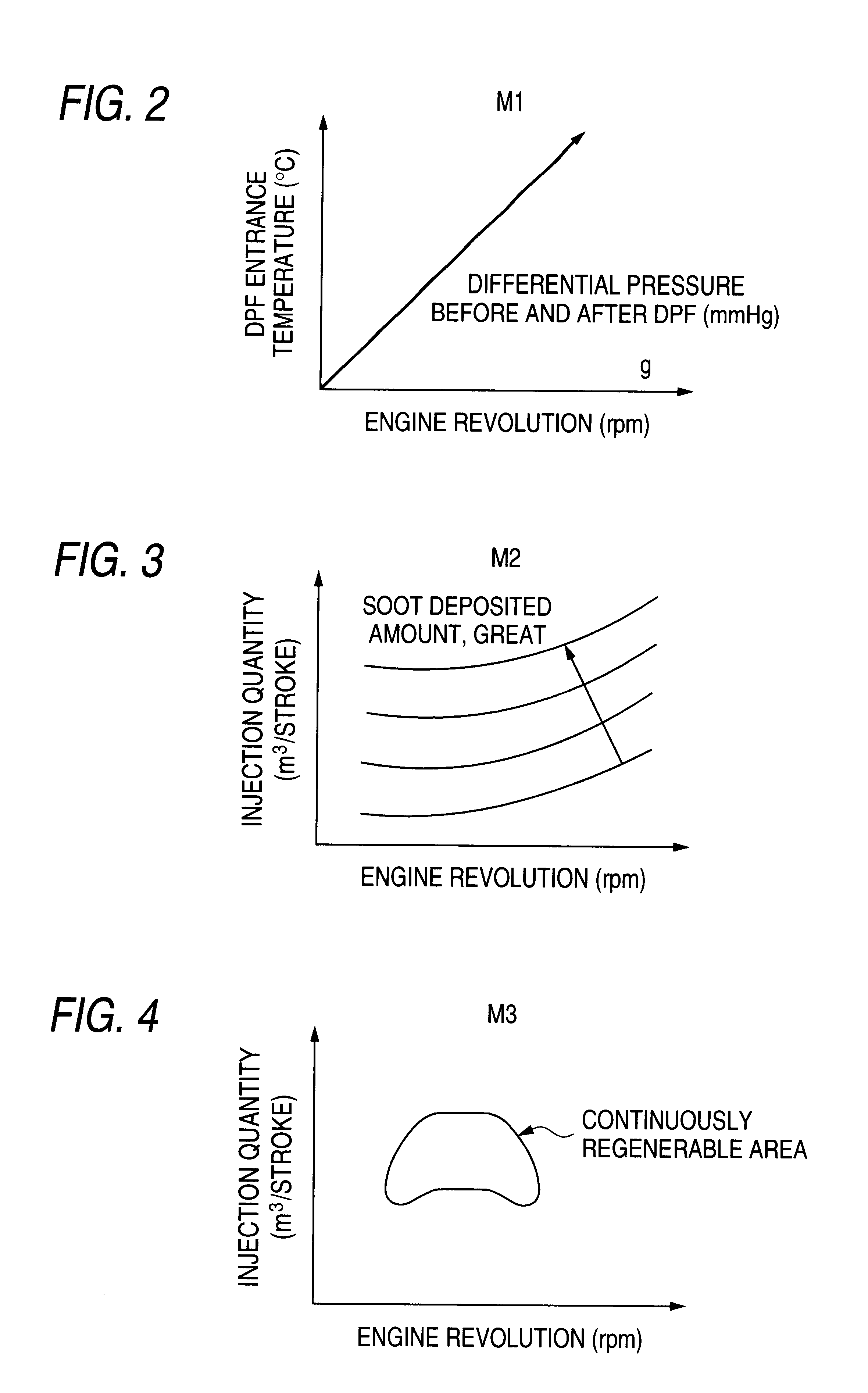
An exhaust emission control device according to one embodiment of the present invention will be described below with reference to the drawings. FIG. 1 is a typical diagram showing the overall configuration of a diesel engine equipped with the exhaust emission control device. FIGS. 2 to 4 are graphs showing a control map for use with the control. Also, FIGS. 5 to 7 are flowcharts for explaining the action. Moreover, FIG. 8 is a control block diagram for explaining the functions.

A diesel engine in this embodiment comprises an engine main body 40, a suction system 2, an exhaust system 3, an Exhaust Gas Recirculation system (EGR system) 44 and a control unit (controller) 14, as shown in FIG. 1.

The suction system 2 comprises a suction pipe 20, a compressor 21, an inter-cooler 22 and a throttle (suction throttle) 23, whereby the air outside the vehicle is forcefully fed into the suction pipe 20 by the compressor 21, cooled by the inter-cooler 22 and introduced into an engine main body 40....


PUM

PropertyMeasurementUnit
temperatureaaaaaaaaaa

Abstract

A control unit activates regeneration assist means, if a specific operating state involving incomplete combustion of particulates by NO2 continues for a predetermined period or more, as a first determination condition, and controls an exhaust gas temperature or a temperature of a catalyst to enhance the conversion efficiency of the catalyst into NO2, thereby continuously regenerating the particulates. The control unit activates forced regeneration means, if a deposited amount of particulates detected by deposited amount detecting means exceeds a predetermined value, as a second determination condition, and controls the exhaust gas temperature or a temperature of a filter to be higher than that of when the regeneration assist means is activated to forcibly regenerate the filter. The control unit activates either the forced regeneration means or the regeneration assist means in accordance with the temperature sensed by temperature sensing means, if the first and second determination conditions are simultaneously established.

Description

This nonprovisional application claims priority under 35 U.S.C. .sctn.119(a) on Patent Application No. 2001-378946 filed in JAPAN on Dec. 12, 2001, which is herein incorporated by reference.1. Field of the InventionThe present invention relates to an exhaust emission control device suitable for a diesel engine.2. Description of the Related ArtAn exhaust gas exhausted from a diesel engine contains particulates (soot) mainly composed of carbon, and various techniques for suppressing this soot to be exhausted to the atmosphere have been developed.As one of those techniques, an exhaust emission control device of the continuous regeneration type is well-known in which an oxidation catalyst and a diesel particulate filter (DPF) are disposed in succession from the upstream side in an exhaust pipe of the diesel engine.In this exhaust emission control device, NO in the exhaust gas is oxidized by the oxidation catalyst to produce NO.sub.2 (2NO+O.sub.2.fwdarw.2NO.sub.2), and the soot (carbon: ...

Claims


Application Information

Patent Timeline
Patent Type & Authority Patents(United States)
IPC IPC(8): F02D41/02F01N3/023F01N9/00F01N3/035F02D41/40F02D41/14F01N7/00F01N7/02F02B37/18F02B37/00F02M25/07F01N3/02B01D46/42F01N3/025F01N3/029F01N13/02
CPCF01N3/0231F01N3/0235F01N3/035F01N9/002F02D41/024F02D41/029F02D41/405F01N13/0097F01N13/009F01N2260/14F02B37/00F02B37/18F02D41/1446F02D2200/0802F02D2200/0812F02D2200/501F02D2200/602F02M25/0707F02M25/0727Y02T10/44Y02T10/26Y02T10/47F02M26/05F02M26/23Y02T10/12Y02T10/40F01N3/023
Inventor MORIMOTO, MANABUOOHASHI, KAZUYATERADA, MIKIO
Owner MITSUBISHI MOTORS CORP
Why Eureka
Try Eureka