
Combined system for removing contaminants from gas effluents

Inactive Publication Date: 2004-03-23
CALDERON DE LOS SANTOS JUAN JOSE
View PDF14 Cites 13 Cited by
  • Summary
  • Abstract
  • Description
  • Claims
  • Application Information

AI Technical Summary

Benefits of technology

Having in mind the drawbacks of the prior art, it is an object of the present invention to provide a combined system for the elimination of pollutants from gaseous effluents of easy and economic construction but with high efficiency and reliability for retaining in a great extent diverse solid pollutant particles suspended in air.
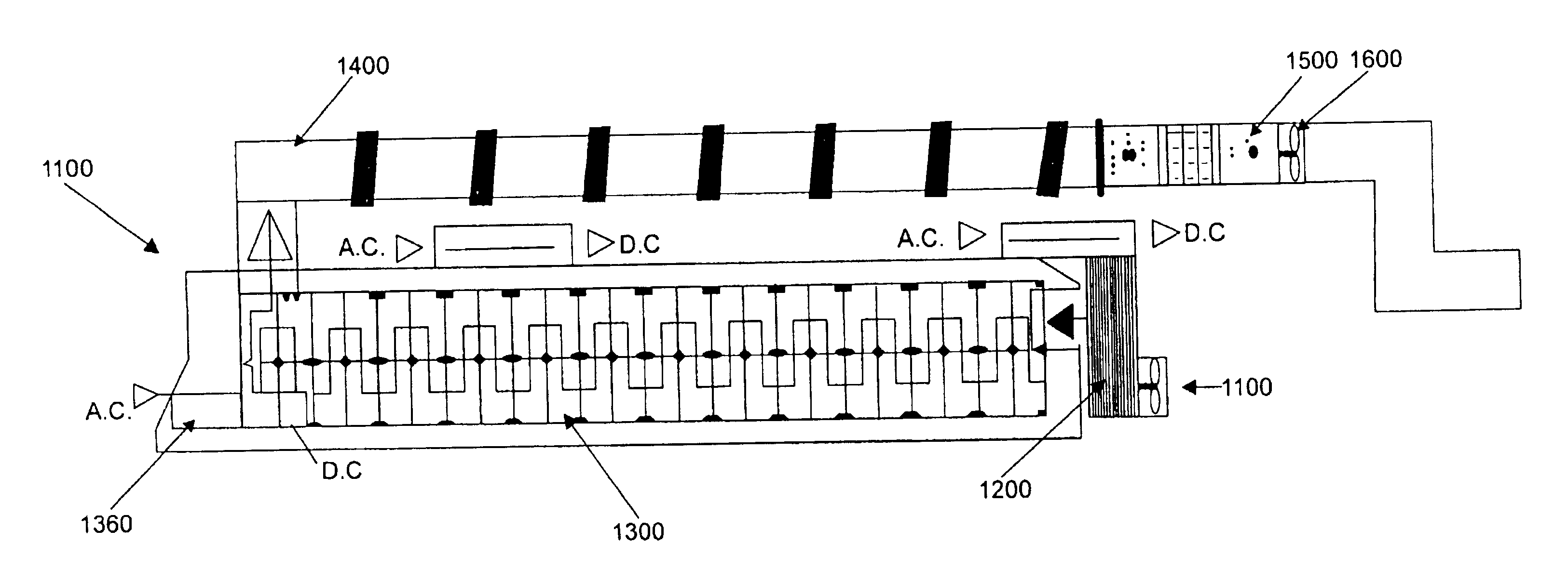
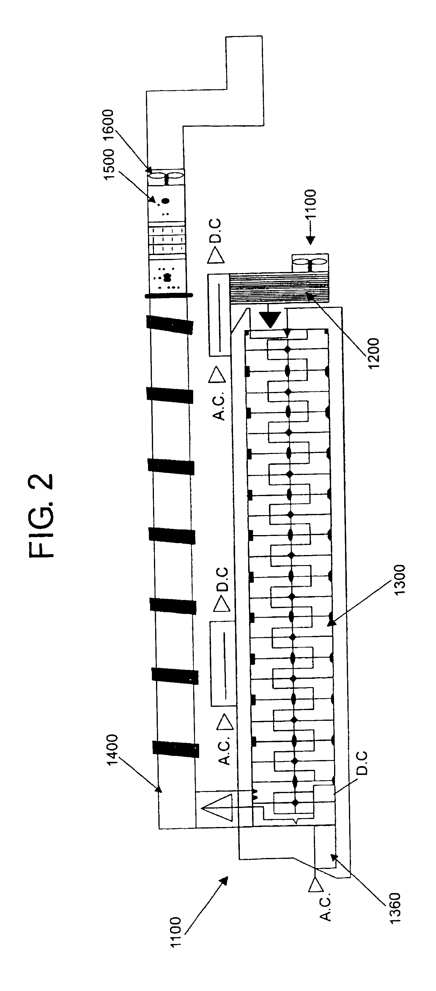
In the described embodiment, the first coupling means 1520 allow to connect module 1500 with module 1400, isolating both modules in order to avoid any electrical interference, while the second coupling means 1530 allow the union of module 1500 with module 1600. In an additional embodiment of the present invention, first and second coupling means 1520 and 1530 have a design that allows the easy release of the electrostatic filter. This is due to the fact that the electrostatic attraction generated by the positive and negative charges causes filters 1511 and 1512 to become saturated by the association of oppositely charged particles with the material thereof, thus making necessary its replacement.

Problems solved by technology

As it can be seen from the latter, air pollutants can also produce pollution of the ground and ecosystems due to the fact that they travel easily and rapidly.
It is quite difficult to characterize the pollution producing sources.
The pollution due to combustion engine driven vehicles is a much bigger problem in big cities, and even more in the largest such as Mexico City.
In developing countries it has been found that environmental pollution comes mainly from industries that throw their wastes illegally during the night, i.e., pollution comes from fixed sources.
This is probably due to the easiness of installation, operation and maintenance and to the pressure exerted by governments over industries, thus forcing them to install apparatus that enable them to comply with the increasingly strict rules in regard to the pollutants emitted to the atmosphere.
However, they show the disadvantage of having a maximum operating temperature of 500.degree. F. and generating pressure drops higher than 4 in H2O, although they can achieve efficiencies around 99% and need little space for its operation.
An additional inconvenient of these filters is the great sensitivity of the bags to humidity, filtration rates and temperature.
Electrostatic precipitators can achieve efficiencies of 99% at optimal conditions, but its performance is still low under non-favorable conditions.
Is worth mentioning, however, that filters in general are only used for eliminating suspended particles and not for eliminating other kinds of pollutants, such as gaseous type pollutants, for example.
However, in this method is required the pollutant to be easily condensed, otherwise it would be maintained as gas and could not be eliminated by this method.
In general terms, most of the current techniques for treating gaseous polluted effluents of high efficiency present the inconvenience of requiring a liquid for the treatment, which in turn has to be post-treated to avoid pollution of effluents and ground.
Additionally, the use of liquids generates corrosion in the apparatus and can be very sensitive to changes in particle properties thus decreasing its efficiency; and in general, they can only be used for certain kinds of pollutants.
On the other hand, the apparatus that need not an additional fluid present low efficiency.
However, the efficiency of these apparatus is rather low and they are barely used for industrial gaseous effluent treatment.
Now then, in regard to mobile sources such as the combustion gases of automobiles, the most used apparatus are those of the catalytic type, which in addition to be expensive due to the noble metal content, they tend to be easily poisoned, thus decreasing its efficiency in a great extent.

Method used


Image

  • Combined system for removing contaminants from gas effluents
  • Combined system for removing contaminants from gas effluents
  • Combined system for removing contaminants from gas effluents

Examples


Embodiment Construction

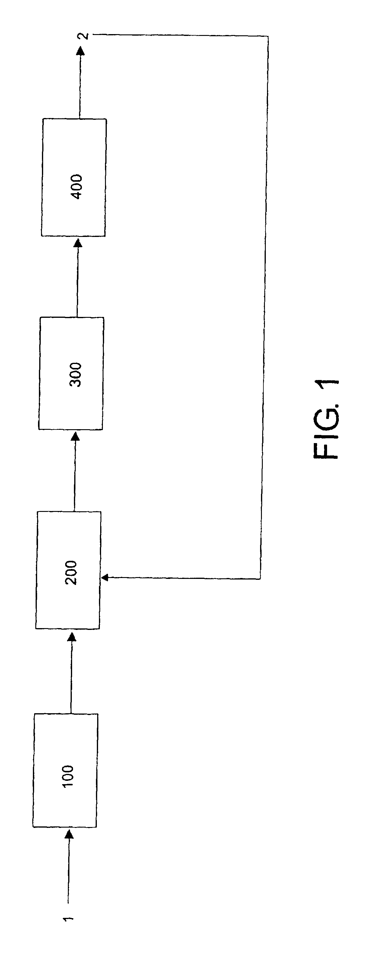
For the execution of the examples, gases coming from various sources were treated in order to observe the effect that the combined system for the elimination of pollutants from gaseous effluents had over the generated gases, as well as the disadvantages of a combined system that does not incorporate the heat diffusion and molecular destabilization and the magnetic molecular rearrangement operations.

Following table 1 is presented, wherein the size of the peaks obtained in accordance with the results of a gas spectrophotometry, using a chromatographic column of the type PORAPAK-N@ 200C at the Nuclear Investigation National Institute (ININ), is shown. Chromatograms showing the presence of the various compounds before and after being treated by diverse methods were obtained. Likewise, the total amounts were determined by means of a column type AT-1000.

Total=Percentage of diminishment of pollutants due to the treatment, as determined by means of column AT-1000.

As may be seen from table 1...


PUM

PropertyMeasurementUnit
Lengthaaaaaaaaaa
Lengthaaaaaaaaaa
Fractionaaaaaaaaaa

Abstract

It is disclosed a combined system for the elimination of pollutants from gaseous effluents of the type that comprises means for carrying out at least one electronic bombardment operation and means for carrying out at least one electrostatic interaction operation, in which a heat diffusion and molecular destabilization operation is performed as a previous treatment in order to restrict the flow of gases in such a way that it causes the gas molecules and suspended particles to tend to split up and electronically destabilize at the time that the temperature of the same gases is reduced; and / or a magnetic molecular rearrangement operation is carried out prior to each electrostatic interaction operation, consisting of subjecting the gases to a magnetic field having such a force that achieve a rearrangement of the sub-particles and heavier molecules thus achieving a selective separation that prepares the gaseous stream for the electrostatic interaction operation. It is described also an apparatus with the system incorporated therein.

Description

The present invention is related to the techniques for the elimination of pollutants, and more particularly, it is related to a combined system for the elimination of pollutants from gaseous effluents.Pollution has existed since man began to modify his environment by using tools, managing fire, and performing agriculture, thus differentiating himself from other predators. For instance, the arrival of agriculture gave place to alterations in the existing ecosystems. However, it was in a very similar way to what happened in natural phenomena.Although such changes in the environment surrounding man are very ancient, it was until the industrial revolution when man obtained enough control over the environment as to deteriorate it. Even though such deterioration is relatively recent with respect to human history, there had to pass almost two hundred years before solutions started to be sought. In view of this, the new challenge that civilization has to face nowadays consists of knowing ho...

Claims


Application Information

Patent Timeline
IPC IPC(8): B01D49/00B03C1/02B03C1/023B03C3/04B03C3/34B03C3/36B03C3/12
CPCB01D49/00B03C1/023B03C3/12B03C3/36
Inventor CALDERON DE LOS SANTOS, JUAN JOSE
Owner CALDERON DE LOS SANTOS JUAN JOSE
Learn More