Method and apparatus for hard machining

Inactive Publication Date: 2004-05-11
ARIZONA STATE UNIVERSITY
View PDF13 Cites 31 Cited by
  • Summary
  • Abstract
  • Description
  • Claims
  • Application Information

AI Technical Summary

Benefits of technology

An improved method and apparatus for combining a comparatively coarse, roughing cut at a high removal rate (in a location of coarse cutting) and a finishing cut at a low removal rate (in a location of finishing cutting) are employed that are useful in hard turning operations. The new method and apparatus make it possible to use a much less expensive tool material such as ceramic in place of PCBN that is now used in hard turning operations. This is accomplished by offsetting the lower tool life of a lower cost tool relative to that of a PCB

Problems solved by technology

The CBN or PCBN is very expensive (comparable to diamond in this respect), while the

Method used


Image

  • Method and apparatus for hard machining
  • Method and apparatus for hard machining
  • Method and apparatus for hard machining

Examples


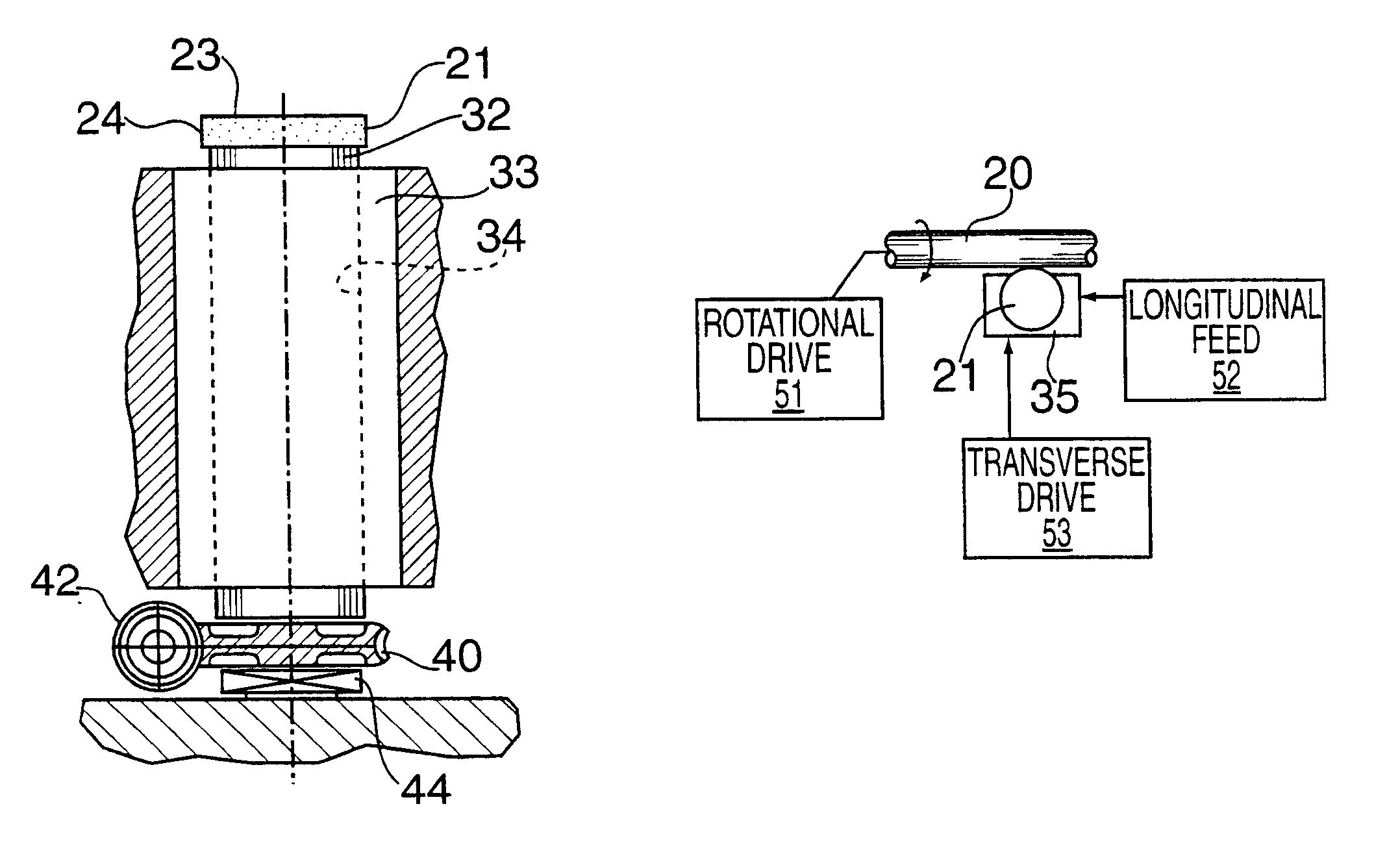
Embodiment Construction

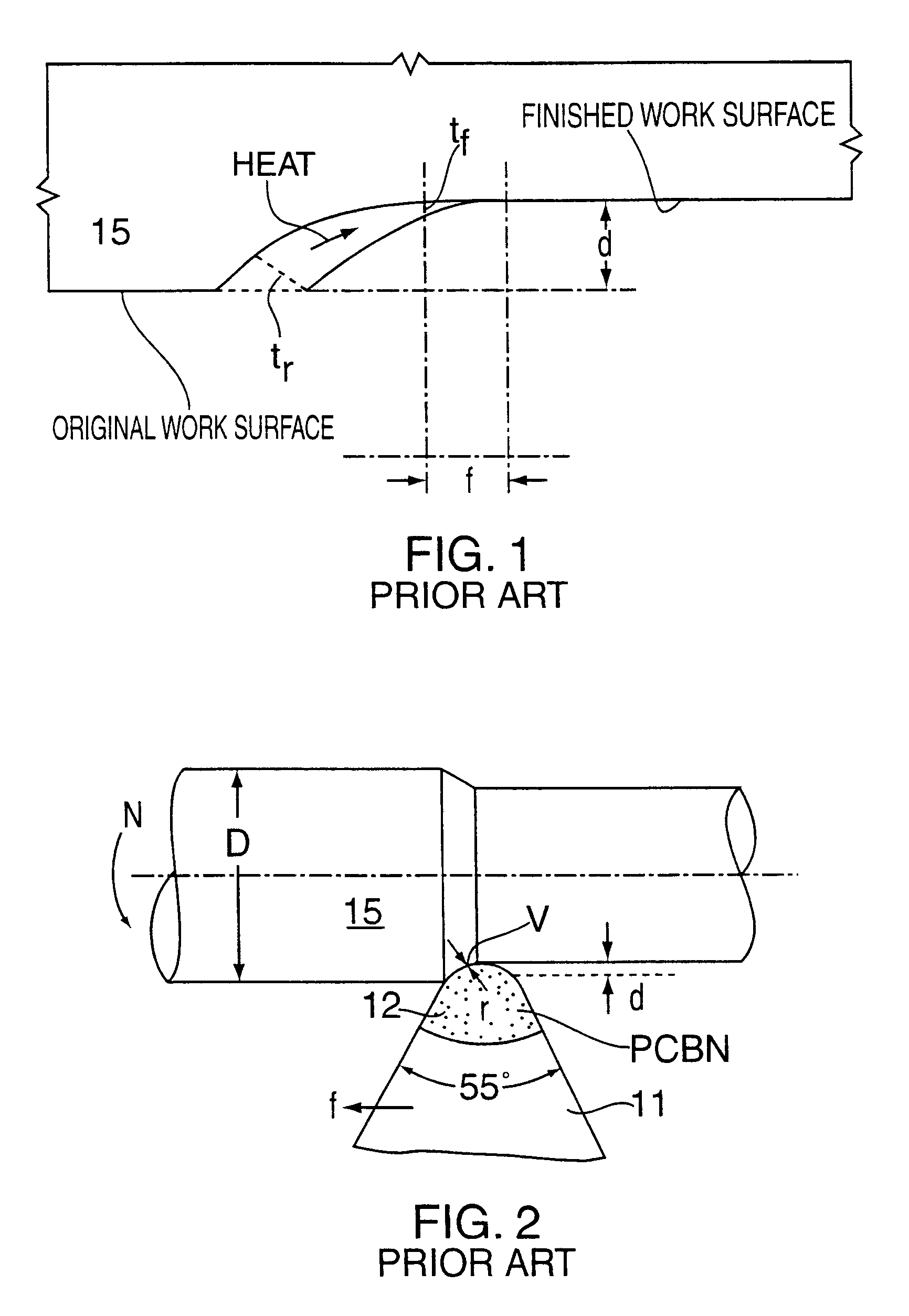
Turning to FIG. 2, at present hard turning is performed using a tool 11 having an expensive polycrystalline CBN insert 12. PCBN is a composite of small single crystal particles bonded together by sintering. A typical application is shown in FIGS. 1 and 2 where:

"f" is the feed rate, inches per rotation (hereinafter "ipr"),

"d" is the depth of cut, inches (hereinafter "in."),

"N" are the rotations per minute (hereinafter "rpm" of a workpiece 15,

"D" is the workpiece diameter, in., "V" is the cutting speed defined as .pi.DN (in. per minute), perpendicular to the paper, and

"r" is the radius (in.) of the tool insert 12.

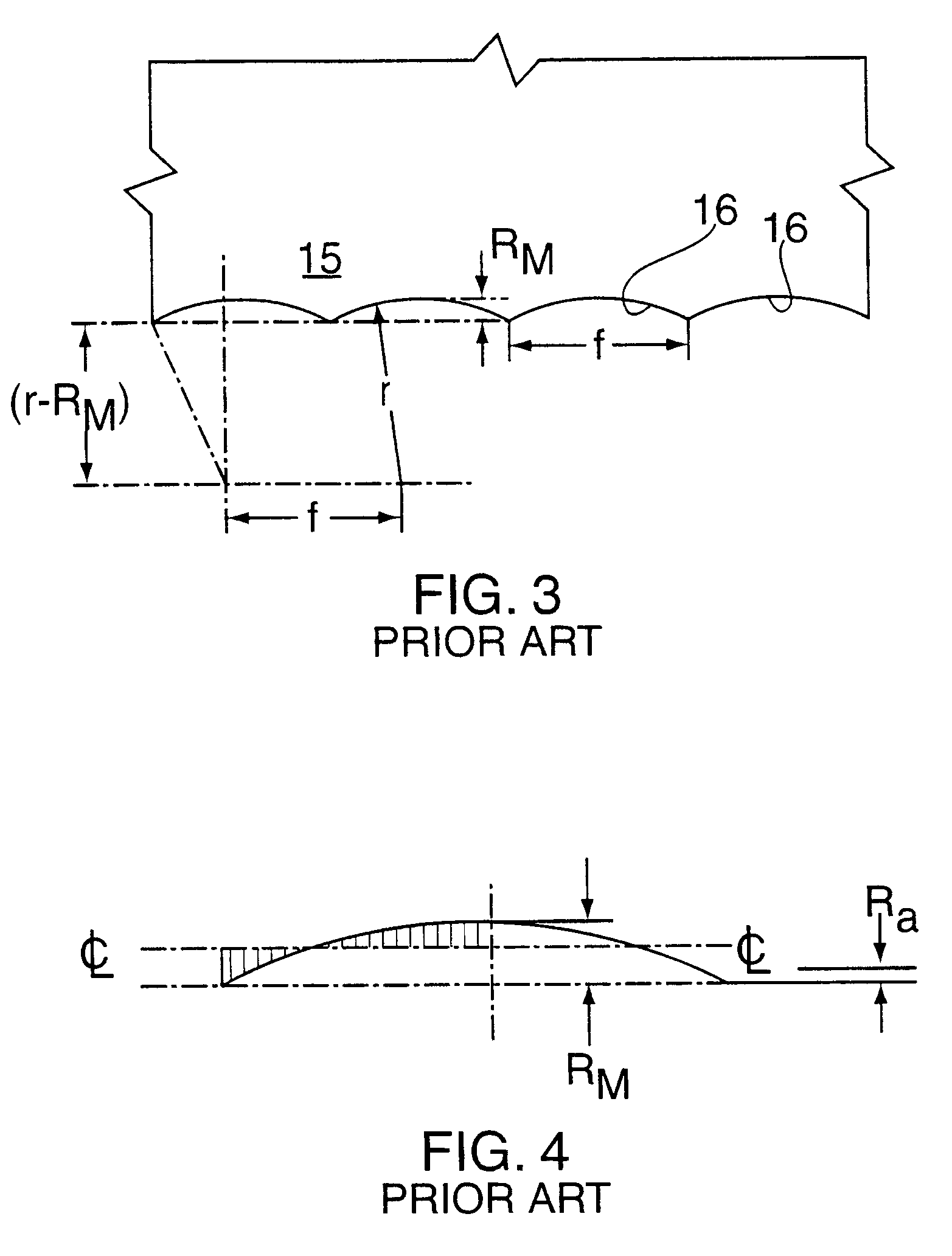
For a sharp tool, and a reasonably rigid machine, the surface finish depends primarily upon a scallop 16 generated by the nose of the tool having a radius r. FIG. 3 shows this scallop 16 with feed (f) greatly magnified relative to r, and where R.sub.m is the depth of the scallop. R.sub.m is called the peak-to-valley roughness. To a good approximation:

R.sub.m =f.sup.2 / 8r (1)

S...


PUM


Abstract

A hard machining process uses a cylindrical tool (21) of ceramic or other hard machining material of comparatively low cost that provides a circular cutting edge to be engaged in cutting relation with hardened workpiece (20) to be machined. As tool cutting edge wear occurs, the tool (21) is rotated through a small angle to bring into contact with the workpiece (20) a fresh portion of the cutting edge. It is not necessary to rotate that tool (21) sufficiently to effect replacement of the entire cutting edge portion in engagement with the tool. Sufficient angular movement of the tool is made to replace that of the cutting edge that has the greatest effect on the finish of the machined workpiece (20), which is the cutting location where the removed chip is thinnest.

Description

This invention relates to a method and apparatus for hard machining a hardened workpiece, and more particularly to such methods and apparatus in which the cutting tool is moved to bring a fresh, unworn portion of a cutting edge into cutting engagement with the workpiece.There is growing interest in a machining operation known as "hard turning" or "hard machining." This involves removing material from a workpiece in a machining operation with the workpiece in a hardened state. In the past, it has been customary to produce parts, such as ball and roller bearings, gears, cams, etc., that must be hardened to decrease wear, by the following sequence of steps:rough machine a part in its soft state,heat treat the part, andrough and finish grind the part to provide desired accuracy and surface finish.By contrast, in hard machining, the hardened part is machined to produce a part in a single operation instead of the more costly sequence indicated above.Hard machining has become an option wit...

Claims


Application Information

Patent Timeline
IPC IPC(8): B23B27/00B23B27/12
CPCB23B27/12B23B2226/18
Inventor SHAW, MILTON C.VYAS, AMITABH
Owner ARIZONA STATE UNIVERSITY
Why Eureka
Try Eureka