Method for producing spectacle lens and lens processing system

a processing system and lens technology, applied in the field of spectacle lens and lens processing system, can solve the problems of degrading production yield, achieve the effects of reducing manpower and inspection time, reducing the variation of decided accuracy, and improving production yield

Inactive Publication Date: 2004-06-01
SEIKO EPSON CORP
View PDF12 Cites 42 Cited by
  • Summary
  • Abstract
  • Description
  • Claims
  • Application Information

AI Technical Summary

Benefits of technology

According to the present invention, since the edging line 31 as the edging mark shown in FIG. 2(a), which is depicted on the lens, functions as a boundary line for appearance inspection, the quality of only the region inside the edging line 31 may be guaranteed, and even if defects are observed in a region outside the edging mark, these defects are negligible. Accordingly, since the appearance quality may be guaranteed only for the region surrounded by the edging line 31, it is possible to significantly reduce a variation in decided accuracy, and to relieve a lens have been regarded as a defective product and hence to significantly improve the production yield. Since it is not required to guarantee the appearance quality of ...

Problems solved by technology

If such an edging mark is not depicted, a region whose quality should be guaranteed is indefinite, and accordingl...

Method used


Image

  • Method for producing spectacle lens and lens processing system
  • Method for producing spectacle lens and lens processing system
  • Method for producing spectacle lens and lens processing system

Examples


example 2

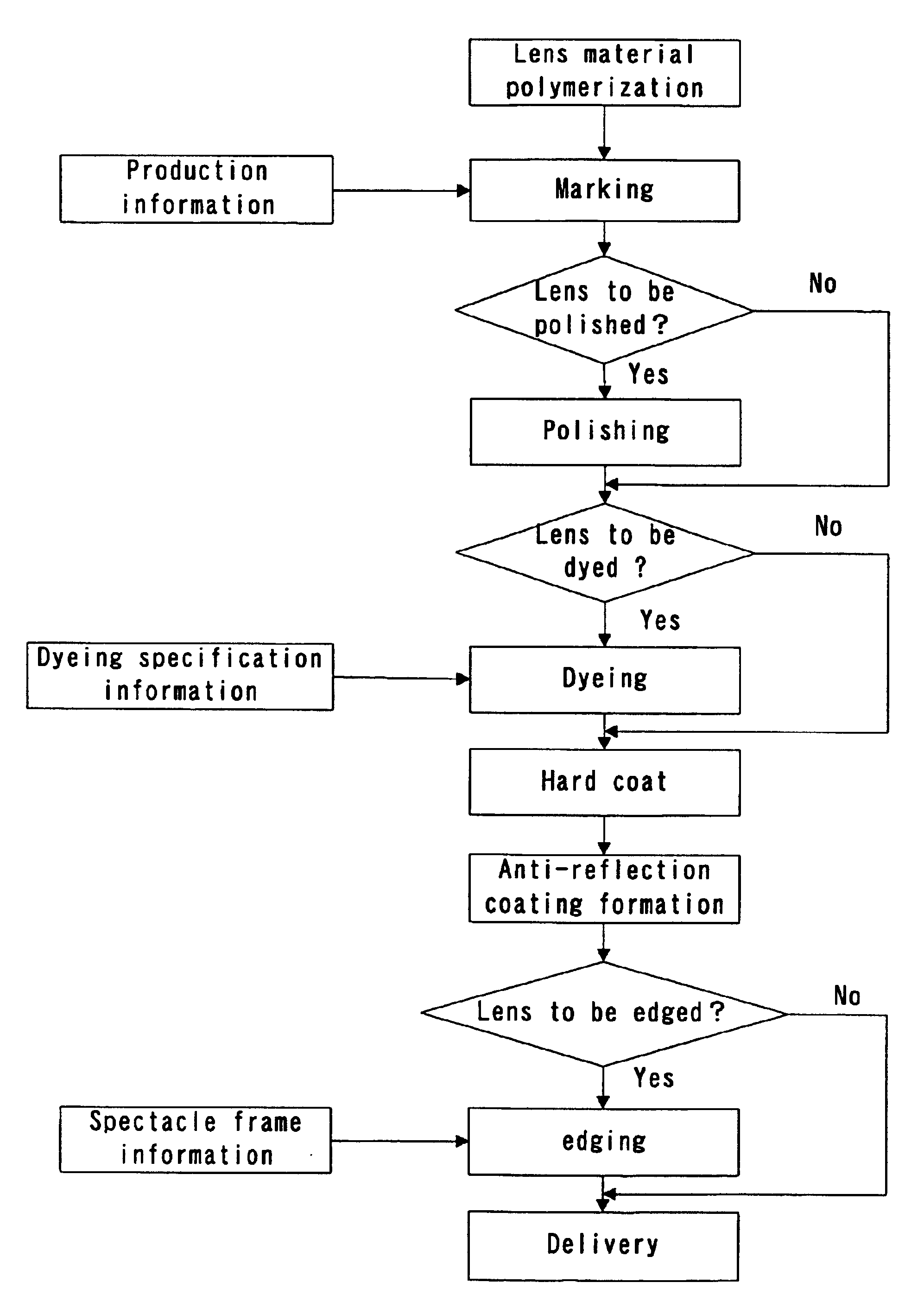
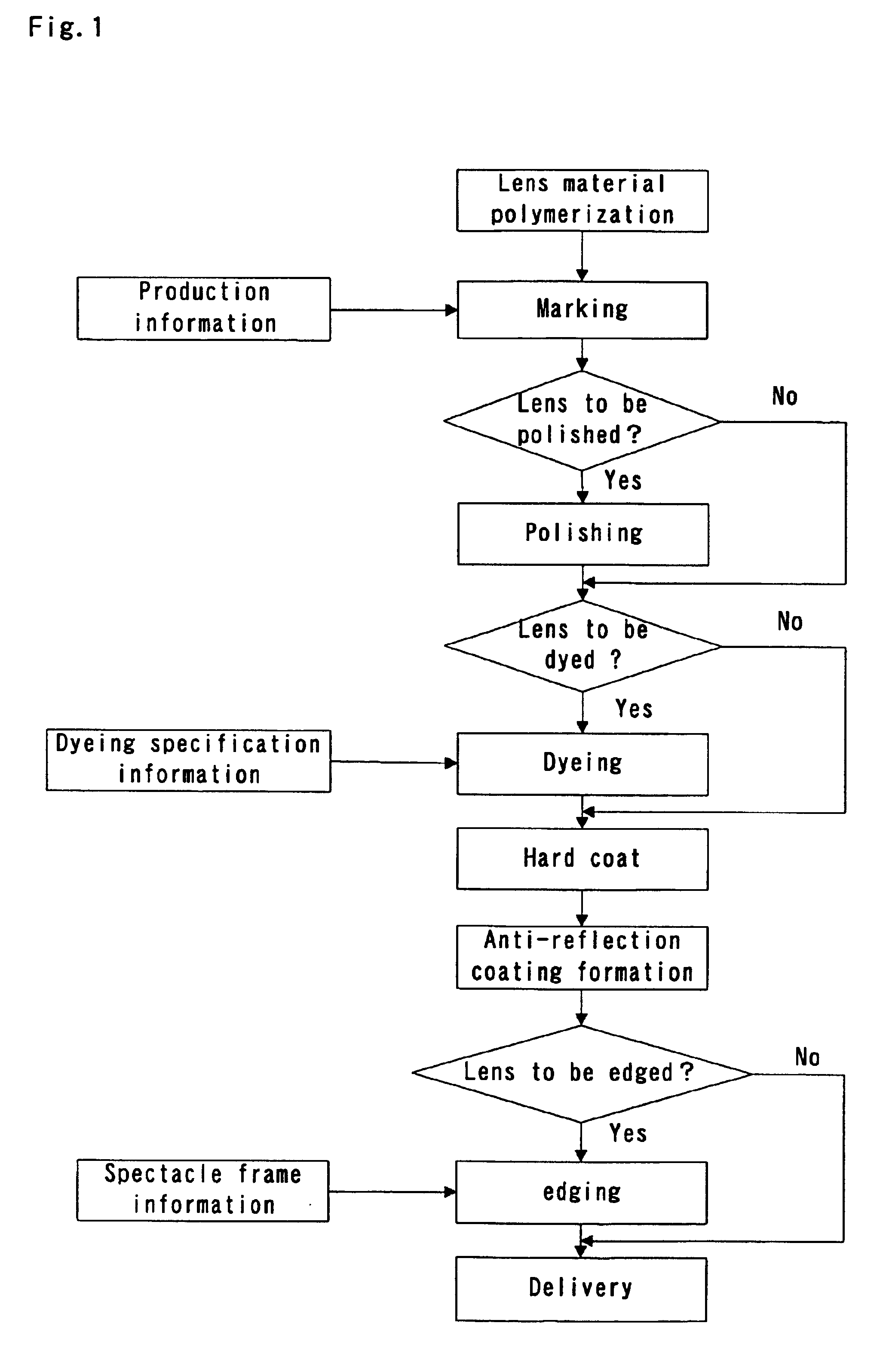
A progressive multi-focal lens made from a plastic material in this example has a specification in which the lens is colorless and is to be subjected to thinning work and edging.

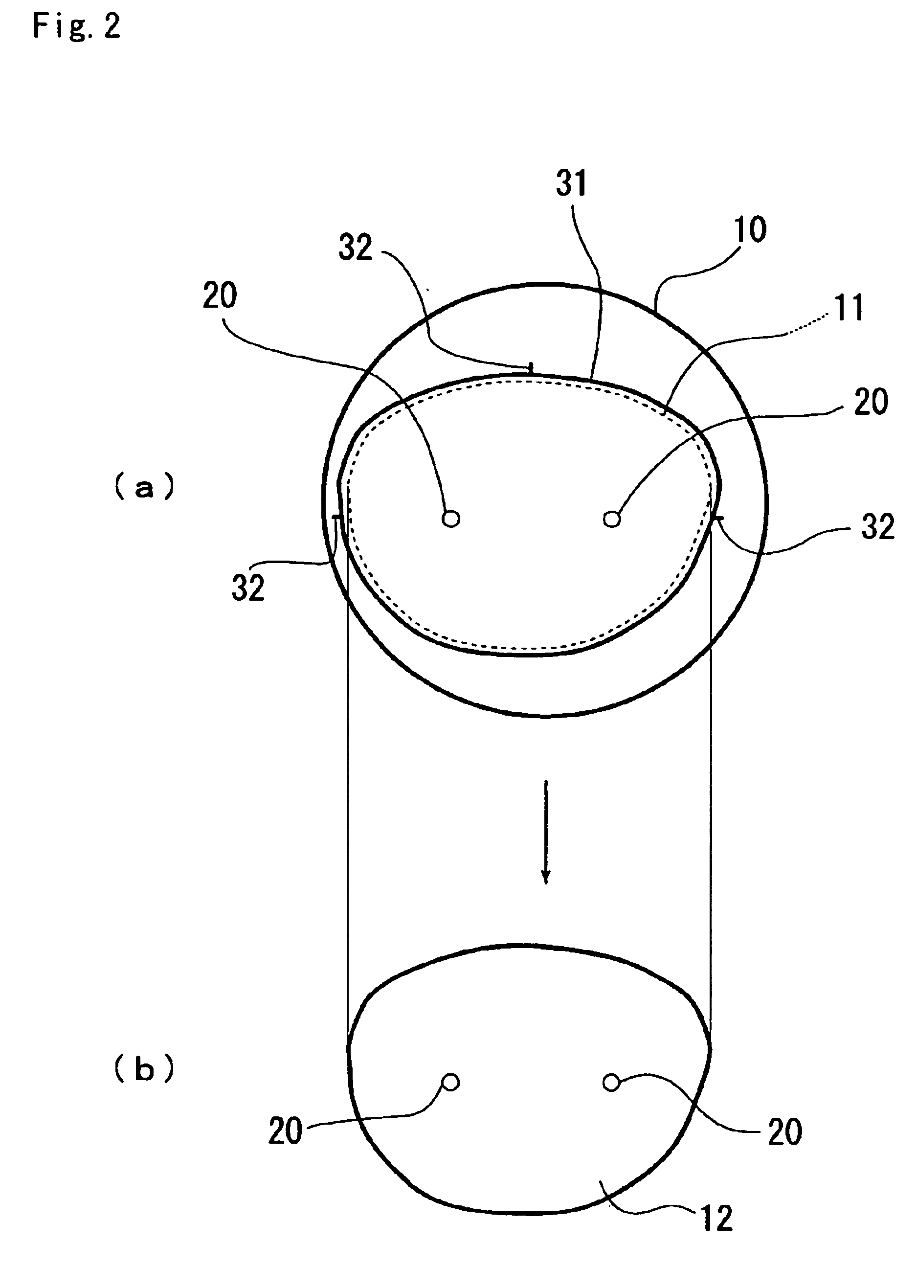
A fitting point as a lens reference position was determined from concealed marks 20 depicted on the outer surface (objective side) of a lens 10b by using the lens processing system shown in FIG. 3. On the basis of the lens reference position, an edging line 31b shown in FIG. 4(b) was depicted by using a carbon dioxide laser as a marking means. Processing data for depicting reference position marks for dyeing were not required to be prepared because the progressive multi-focal lens in this example was specified to be colorless.

At a polishing step, the progressive multi-focal lens was formed into a specific positional accuracy, whereby a lens having an outside diameter 13 smaller than that of the original lens 10b was obtained. The lens was then polished to have a desired polishing appearance. At this polishin...


PUM

PropertyMeasurementUnit
Lengthaaaaaaaaaa
Shapeaaaaaaaaaa

Abstract

Production information such as an edging mark 31 indicating a region of a lens remaining after edging and reference position marks 32 are depicted in a region, to be cut off by the edging, of a surface of a lens 10 for spectacles. Any production information does not remain on the finished lens 10 after the edging. A lens processing system 100 includes a reference position detecting apparatus (120 and 130) for detecting a reference position of a spectacle lens, and a marking apparatus (170, 160, 150 and 110) for depicting production information of the lens on a specific surface of the spectacle lens on the basis of the reference position information obtained by the reference position detecting apparatus (120 and 130).

Description

The present invention relates to a method for producing a spectacle lens and a lens processing system, and particularly to a method for producing a spectacle lens, which method is improved in production yield, and a lens processing system used for the production method.Spectacles have been fabricated in spectacle shops as follows: namely, circular spectacle lens have been subjected to edge cutting work called "edging" in matching with inner shapes of openings of a spectacle frame selected by a user, and the edged lenses thus obtained have been fitted in the openings of the spectacle frame.In recent years, however, because of the lack of the number of laborers skilled in works of edging and inserting the edged lenses in spectacle frames and employed in spectacle shops, there have been strong demands for lens makers to process lenses until edging and deliver the edged lenses to retail shops.On the other hand, plastic lenses having a merit easier to be dyed are superior in fashion and ...

Claims


Application Information

Patent Timeline
IPC IPC(8): B24B13/005B24B9/14B24B9/06
CPCB24B9/14B24B9/148B24B13/0055
Inventor MIYAZAWA, MAKOTO
Owner SEIKO EPSON CORP
Why Eureka
Try Eureka