
Motor protection trip unit

a technology of trip unit and motor, which is applied in the direction of protective switch details, circuit-breaking switches, switches with electromagnetic release, etc., can solve the problems of increasing the potential of unnecessary motor trips, reducing the accuracy of flapper return systems, and reducing the force. effect of current flow to the motor

Inactive Publication Date: 2004-06-01
GENERAL ELECTRIC CO
View PDF9 Cites 10 Cited by
  • Summary
  • Abstract
  • Description
  • Claims
  • Application Information

AI Technical Summary

Benefits of technology

In another aspect, a method of operating a motor is provided. The method includes providing a rated current to the motor through a circuit breaker that includes a tripping assembly, sensing a low current three times rated current and a high current of twenty times rated current with a motor protection trip unit that is coupled to the circuit breaker and the tripping assembly, and tripping the motor protection trip unit when an overcurrent condition is sensed such that current flow to the motor is prevented.

Problems solved by technology

However, because the spring force may diminish over time, accurate repeatability of such a flapper return system may diminish.
Eventually, continued operation of such a return spring system may cause a disengagement of the latching system, thus increasing a potential of unnecessary motor trips.
Furthermore, because of space considerations, the air gap may not be defined wide enough to satisfy the initial desired high current settings, and as such, the circuit breaker may trip at a lower current setting that desired.

Method used


Image

  • Motor protection trip unit
  • Motor protection trip unit
  • Motor protection trip unit

Examples


Embodiment Construction

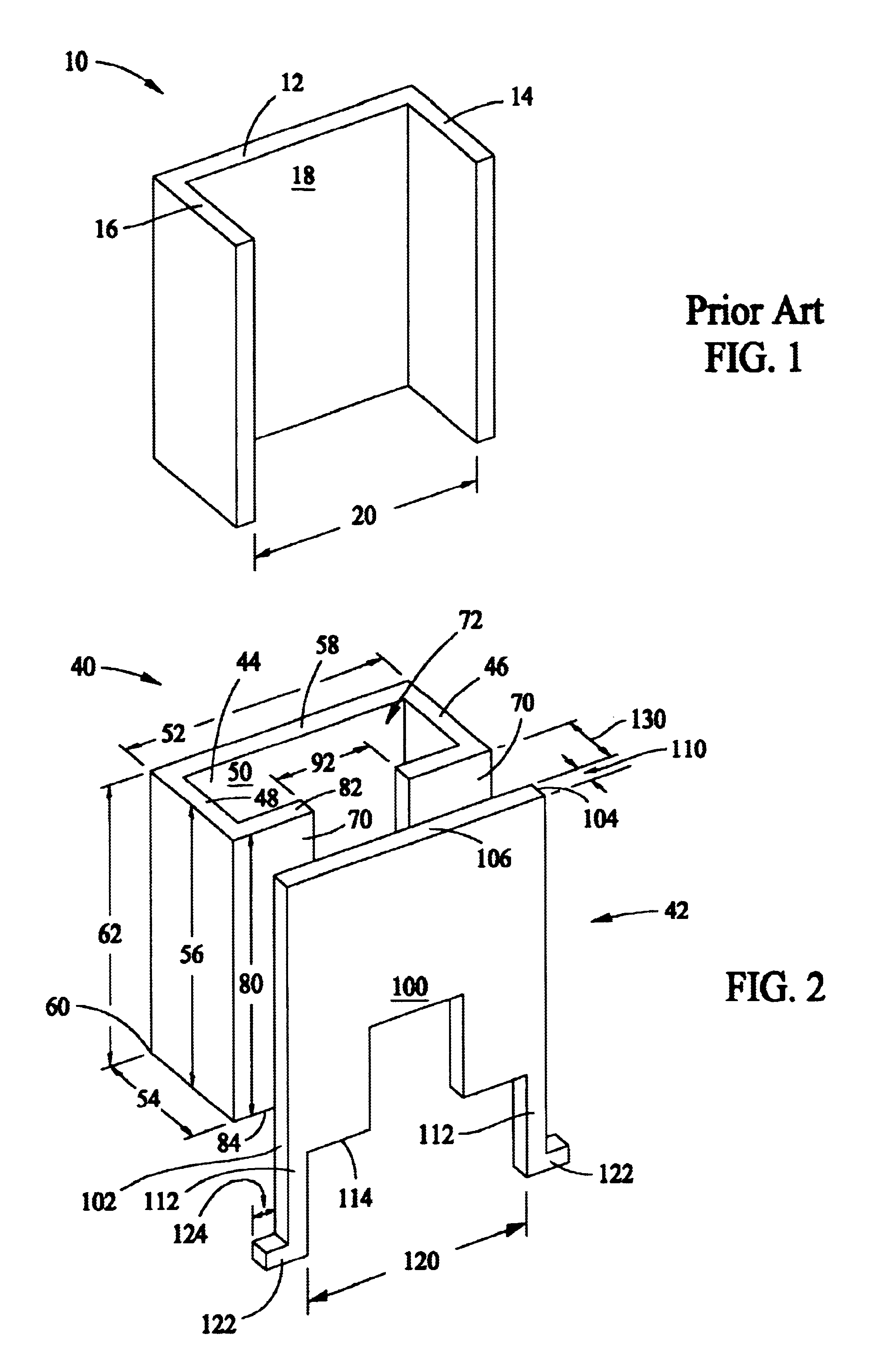
FIG. 1 is a perspective view of a known yoke 10 for use with a motor protection trip unit (not shown). Yoke 10 includes a body 12, a first side 14, and a second side 16. First and second sides 14 and 16, respectively, extend substantially perpendicularly from a front side 18 of body 12 such that a yoke gap 20 is defined between first and second sides 14 and 16, respectively.

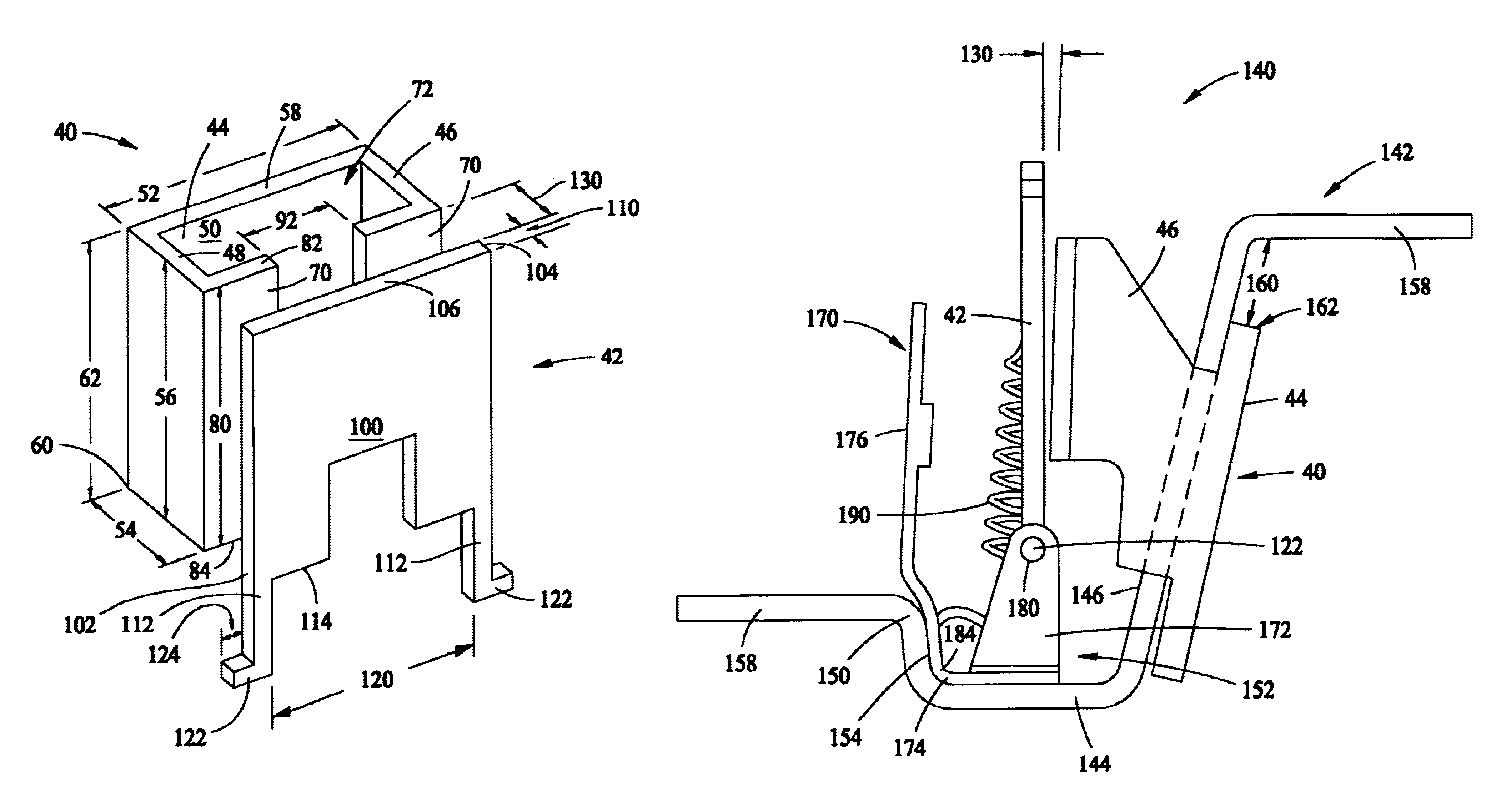
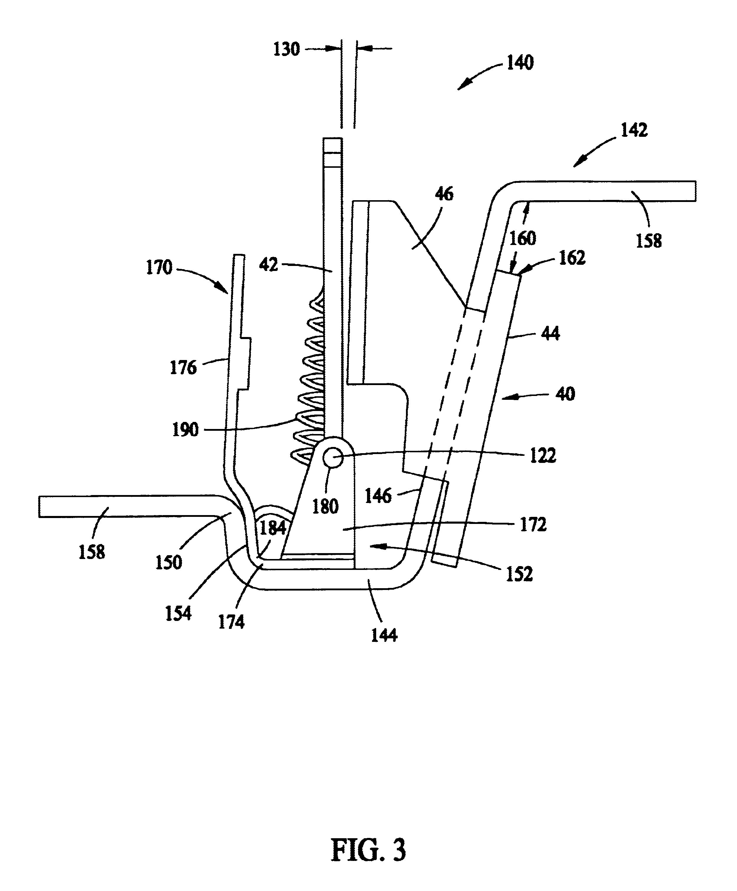
FIG. 2 is a perspective view of a yoke 40 and a flapper 42 for use with a motor protection trip unit (not shown in FIG. 2). Yoke 40 has a body 44, a first sidewall 46, and a second sidewall 48. In one embodiment, yoke 40 is fabricated from a metallic material. Sidewalls 46 and 48 are substantially parallel to each other, and extend substantially perpendicularly from a front side 50 of body 44 to define a width 52 for yoke 40. Yoke 40 also has a length 54 measured with respect to sidewalls 46 and 48. In the exemplary embodiment, sidewalls 46 and 48 are identical, and each has a height 56 measured between an upper ...


PUM


Abstract

A motor protection trip unit for a circuit breaker includes an electrically conductive strap, a yoke including a body including a first side wall, a second side wall, a third side wall, and a fourth side wall. The third side wall extends between the first and second side walls, the fourth side wall extending from the first and second side walls and comprising a yoke gap extending therethrough. A motor protection trip unit for a circuit breaker also includes a flapper holder coupled to the strap, a flapper pivotally coupled to the flapper holder, and a biasing mechanism coupled between the flapper holder and the flapper. The biasing mechanism is configured to maintain the flapper a distance from the yoke such that a yoke-flapper gap is defined between the yoke and the flapper.

Description

BACKGROUND OF THE INVENTIONThis invention relates generally to circuit breakers, and more particularly, to motor circuit breakers including a magnetic trip unit.Circuit breakers are used to provide protection against very high currents produced by short circuits. At least some known circuit breakers include trip units which include a rotationary stator-armature system and a stator-flapper gap system. The stator-flapper gap system is variable to control a gap within the trip unit to facilitate overcurrent trip protection for different trip settings. More specifically, because a magnitude of a low current setting is smaller than that of a high current setting, the gap is defined more narrowly for low current protection, and larger for higher current protection.To accomplish varying the gap, flapper return springs are used in an arrangement such that the restoring moment is increasing with a decreasing gap. However, because the spring force may diminish over time, accurate repeatabilit...

Claims


Application Information

Patent Timeline
Patent Type & Authority Patents(United States)
IPC IPC(8): H01H71/24H01H71/12
CPCH01H71/2472
Inventor DAEHLER, CHRISTIANSAHU, BIRANCHIDANTULURI, VARMA S PO'KEEFFE, TOM
Owner GENERAL ELECTRIC CO
Learn More