Microwave stripline applicators

a technology of microwave stripline and applicator, which is applied in the direction of waveguides, transit-tube circuit elements, structural circuit elements, etc., can solve the problems of reducing the scale of coaxial applicators, reducing the efficiency of coaxial applicators, and not being optimal for small discharges

Inactive Publication Date: 2004-07-06
BOARD OF TRUSTEES OPERATING MICHIGAN STATE UNIV
View PDF9 Cites 18 Cited by
  • Summary
  • Abstract
  • Description
  • Claims
  • Application Information

AI Technical Summary

Problems solved by technology

However, the applicator technologies that were developed to create large discharges, are not optimal for the formation of small discharges.
If the excitation frequency is raised the waveguide and cavity applicators become smaller and thus become more difficult to fabricate.
While this applicator has the ability to create very small discharges it is unlikely that the coaxial applicator can be scaled down to dimensions that enable its fabrication on a chip.
However the microwave applicator coupling technology described herein is fundamentally different from that recently described by Bilgic et al.
Thus this stripline applicator coupling method is similar to earlier developed, nonstripline applicators and therefore has some of the same fundamental limitations such as limited discharge variability, stability problems, difficulty in matching, and the need for variable tuning.
The discharge is located only inside the applicator and thus the discharge size is also limited to the applicator size.
However, variable tuning may be difficult to achieve and thus may be impractical in microwave stripline applicators.

Method used


Image

  • Microwave stripline applicators
  • Microwave stripline applicators
  • Microwave stripline applicators

Examples


Embodiment Construction

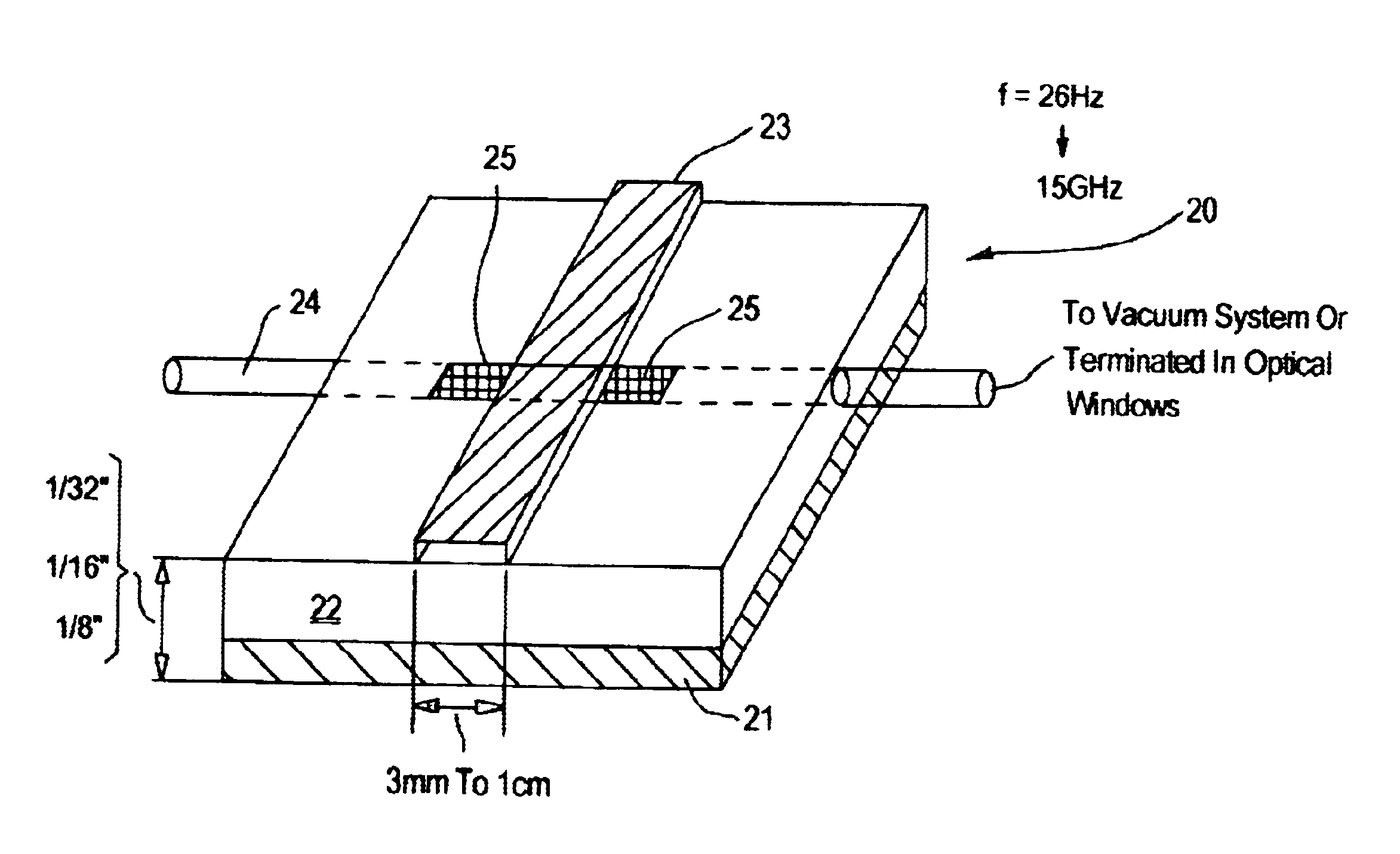
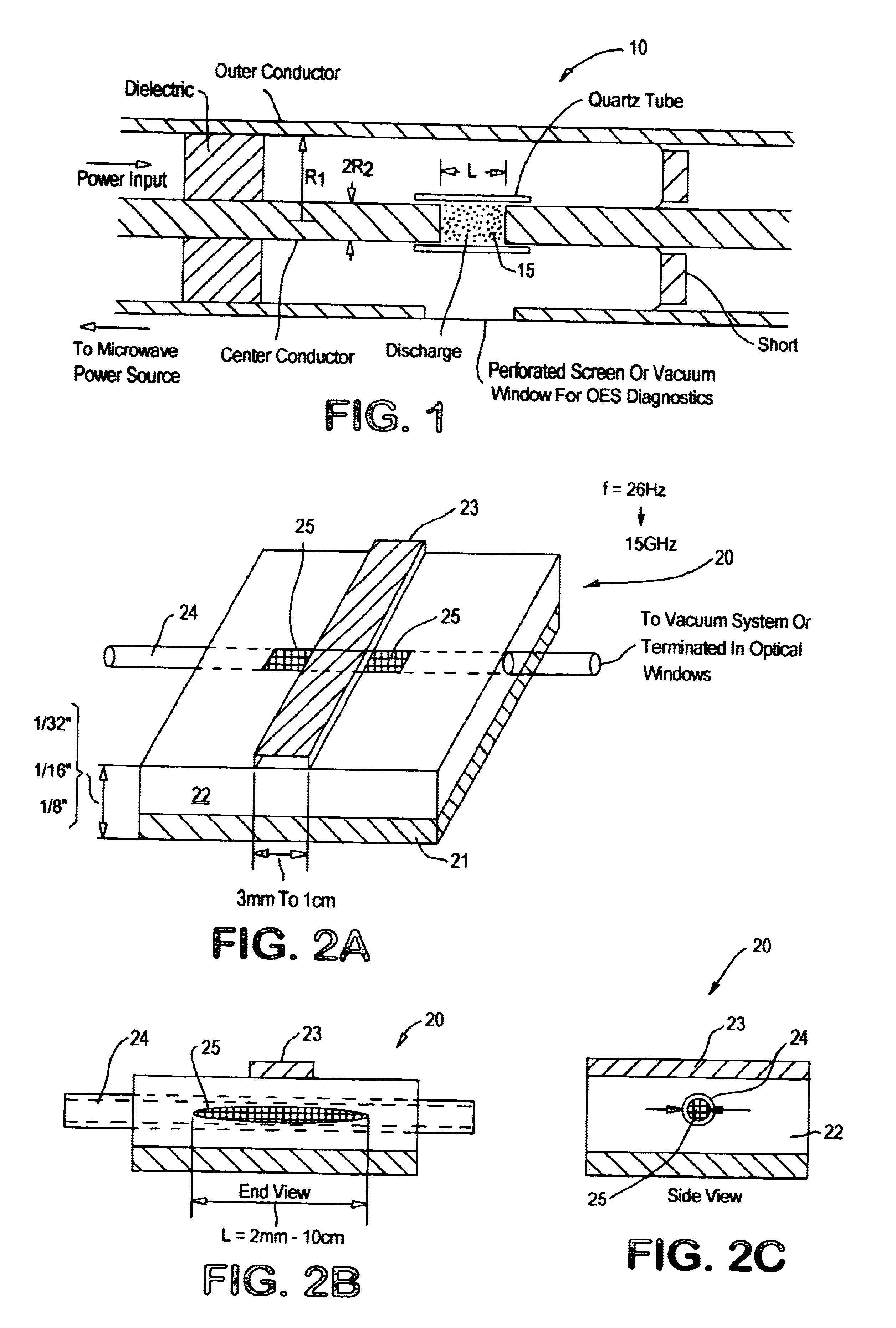
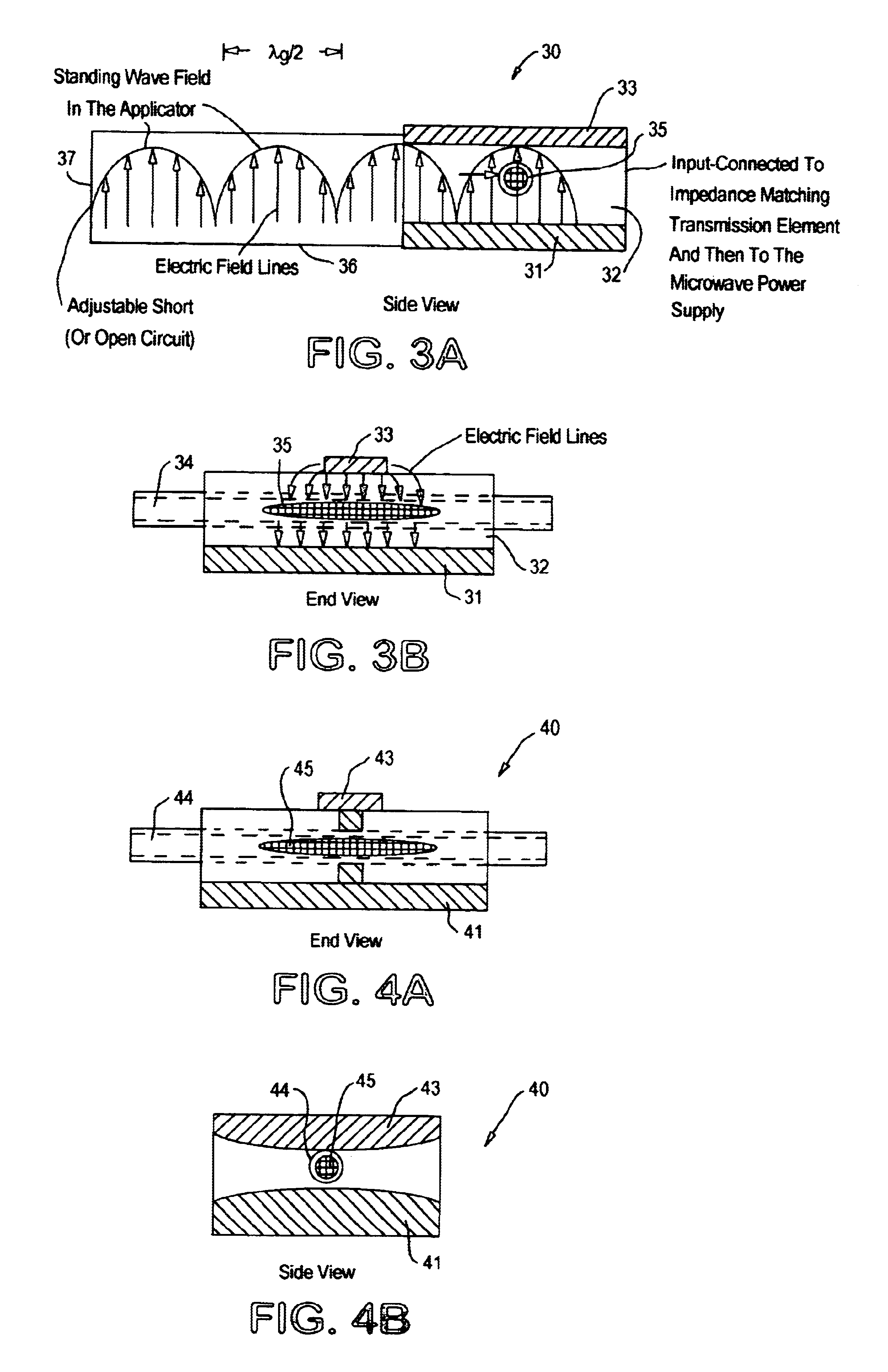
The present invention relates to new applicator technologies that enable the excitation of very small microwave discharges. Discharge dimensions range from a few millimeters down to or even less than a few hundred microns. Additionally the applicator technology that is described utilizes stripline circuits and coupling techniques. Thus excitation frequencies can vary from a few 100 MHz to 10-30 GHz, and possibly even higher frequencies. Microwave applicator geometries are described that enable the matching and focusing of microwave energy into very small volumes. Since .lambda.>>d the electromagnetic focusing can be understood by using transmission theory and quasistatic electromagnetic circuit models.

The possibility of higher frequency excitation has the additional benefit of creating discharges with very high plasma densities. For example, if plasma resonators are formed where ##EQU5##

then the excitation of the discharge at 10 to 30 GHz will create a plasma with a density of appro...


PUM

PropertyMeasurementUnit
thickaaaaaaaaaa
thickaaaaaaaaaa
widthaaaaaaaaaa

Abstract

An apparatus and method which maintains plasma discharges (for instance 25) in containers (for instance 20) which have an internal section of 1 cm or less in width are described. The very small cross-section plasma discharges are useful in MEMS devices, in spectrometers and in spectroscopy.

Description

(1) Field of the InventionThe present invention relates to stripline microwave applicators particularly for creation and maintenance of mini and micro microwave (plasma) discharges. The apparatus and methods described are directed toward efficiently creating and precisely controlling very small microwave discharges (plasmas). These discharges have typical physical dimensions, d, that are less than a millimeter and as small as a few tens of microns. The free space wavelength, .lambda., of microwave energy (300 MHz-30 GHz) varies from one meter to one centimeter and thus .lambda. is much greater than d throughout the entire microwave frequency spectrum. In particular, the present invention relates to an apparatus wherein the stripline conductors that couple microwave energy are transverse to the microwave discharge, and preferably with a container for generating the plasma so that the plasma extends beyond the stripline excitation region.(2) Description of Related ArtIt is also well k...

Claims


Application Information

Patent Timeline
Patent Type & Authority Patents(United States)
IPC IPC(8): H05H1/24
CPCH05H1/24H05H1/46H05H1/4622
Inventor GROTJOHN, TIMOTHY A.ASMUSSEN, JESWIJAYA, ANDY
Owner BOARD OF TRUSTEES OPERATING MICHIGAN STATE UNIV
Why Eureka
Try Eureka