Electronically controlled prosthetic knee

a prosthetic knee and electric control technology, applied in the field of prosthetic joints, can solve the problems of unreliable damping performance, difficult control, changing frictional characteristics,

Inactive Publication Date: 2004-07-20
MASSACHUSETTS INST OF TECH
View PDF48 Cites 231 Cited by
  • Summary
  • Abstract
  • Description
  • Claims
  • Application Information

AI Technical Summary

Benefits of technology

The stance phase 20 begins at heel-strike 24 when the heel touches the floor or supporting ground surface and the stance knee begins to flex slightly. This flexion allows for shock absorption upon impact and also maintains the body's center of gravity at a more constant vertical level during stance.
Also advantageously, the optimized thinness of the MR fluid gap between adjacent rotors 220 and stators 230 provides a higher maximum torque, a wider dynamic torque range and requires less energy consumption, preferably about 10 Watts or less. This adds to the efficiency and practicality of the MR actuated prosthetic knee 210 of the present invention and also saves on cost since a lower wattage and / or less complex power source can be used.

Problems solved by technology

Though dry friction brakes can generally provide a substantial torque range for their size, undesirably, they are often difficult to control.
After extended use, the frictional pads tend to wear, thereby changing the frictional characteristics of the brake and the torque response for a given commanded torque.
Disadvantageously, this can cause unreliable damping performance, and hence adversely affect the gait of the amputee and also cause discomfort to the amputee.
Consequently, dry friction brakes may need frequent servicing and / or replacement which undesirably adds to the cost.
Under high loading conditions, viscous torque brakes are susceptible to leakage of hydraulic fluid and possibly other damage due to excessive pressure build-up.
Disadvantageously, this can result in an irreversible state, since once the brake unit is overloaded it cannot return to normal.
Therefore, such a viscous torque brake for a prosthetic joint is prone to catastrophic failure, and hence can be unreliable and detrimental to the safety of an amputee.
Disadvantageously, a MR brake operated in the "valve mode" also develops internal fluid pressure buildup, and hence is still susceptible to traditional pressure-induced failure, thereby putting the amputee at risk.
In contrast, if a 40:1 step-up transmission is used to increase the viscous torque, disadvantageously, not only is the system reflected inertia magnified by a factor of about 1600, but the system weight, size and complexity are undesirably increased.
This results in forty flux interfaces or fluid gaps in which the magnetorheological (MR) fluid resides.
Moreover, costly and / or relatively complex components such as pressure bearings and the like need not be utilized to provide a reliable seal.

Method used


Image

  • Electronically controlled prosthetic knee
  • Electronically controlled prosthetic knee
  • Electronically controlled prosthetic knee

Examples


Embodiment Construction

FIGS. 26 to 51 show several preferred embodiments having features and advantages in accordance with the present invention. For purposes of clarity and brevity of disclosure only certain features of these embodiments are discussed below and it is to be understood that other features are obvious from the drawings and / or are embodied in the description of the preferred embodiments as set forth above.

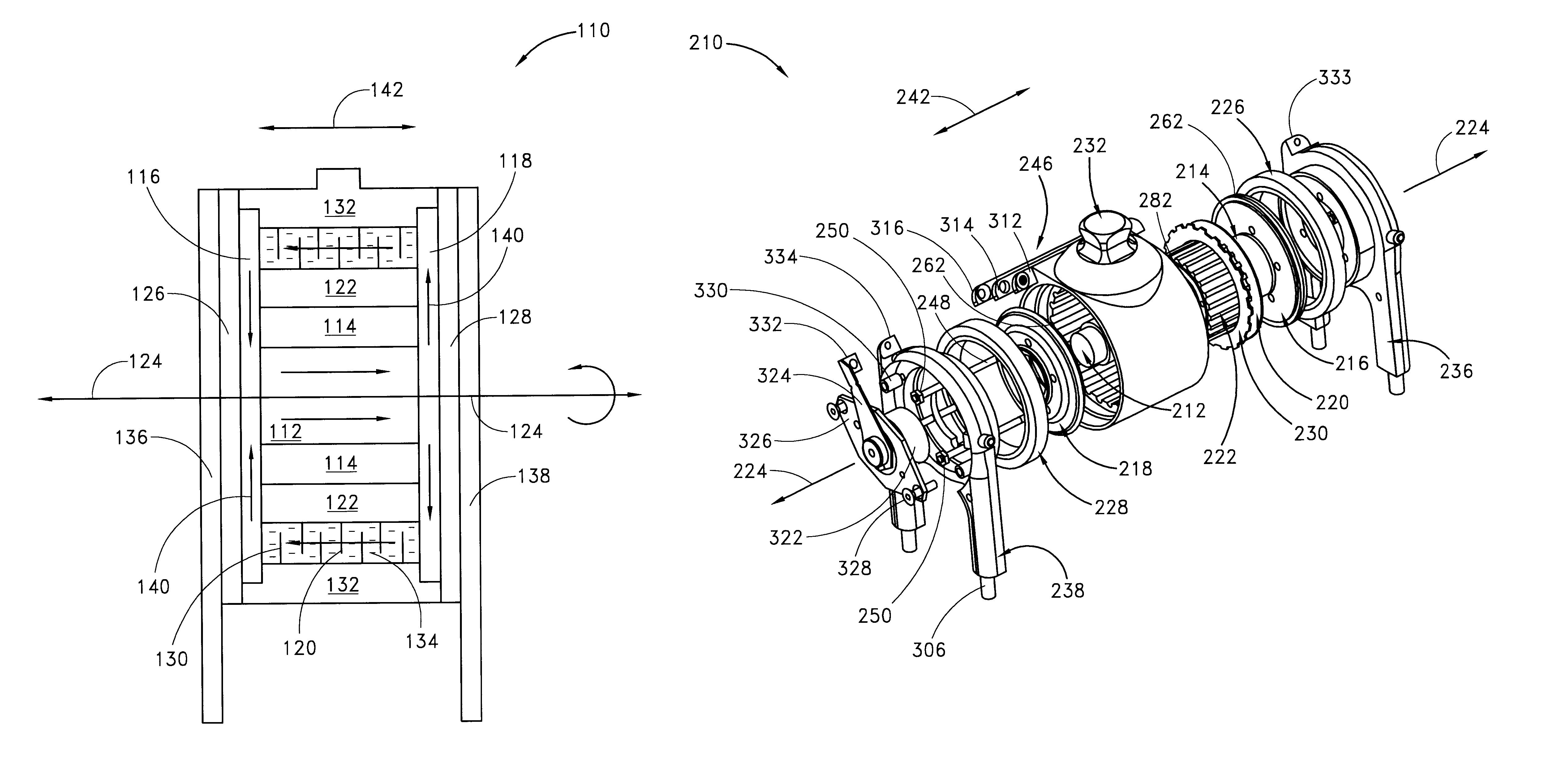
FIGS. 26-28 show one preferred embodiment of a substantially central core 412 of a magnetorheologically actuated prosthetic knee of the present invention. The core 412 preferably comprises a beveled or tapered surface 336 and a shoulder or step 338 at respective ends of respective core portions 452, 454 to facilitate mating engagement or mechanical connection with associated core side plates 416, 418 (shown in FIGS. 29-36). Thus, the core 412 rotates as the side plates 416, 418 rotate.

Preferably, the core 412 comprises an iron-cobalt (FeCo) high magnetic saturation alloy. In one preferred e...


PUM


Abstract

The present invention relates to a variable-torque magnetorheologically actuated prosthetic knee which utilizes a plurality of interspersed and alternating rotors and stators to shear magnetorheological fluid in gaps formed therebetween. Advantageously, by operating in the "shear mode" there is substantially no or negligible fluid pressure buildup or change. Moreover, the multiple MR fluid gaps or flux interfaces desirably allow for the production of a large torque at low speed-eliminating the need for a transmission-and also for a wide dynamic torque range. One embodiment of the invention allows the rotors and / or stators to close the gaps therebetween to create a frictional torque component, thereby forming a "hybrid" braking system which provides a total torque or damping which is a combination of viscous torque and frictional torque.

Description

1. Field of the InventionThe present invention relates to prosthetic joints in general and, in particular, to controllable braking systems for prosthetic knee joints.2. Description of the Related ArtThree types of variable-torque brakes have been employed in prosthetic knees in the past: (i) dry friction brakes where one material surface rubs against another surface with variable force; (ii) viscous torque brakes using hydraulic fluid squeezed through a variable sized orifice or flow restriction plate; and (iii) magnetorheological (MR) brakes or dampers where MR fluid (containing small iron particles suspended in the fluid) is squeezed through a fixed orifice or flow restriction plate, with viscosity of the fluid being varied in response to an applied magnetic field. Each of these technologies, as conventionally practiced in the field of prosthetics, can pose certain disadvantages.Though dry friction brakes can generally provide a substantial torque range for their size, undesirably...

Claims


Application Information

Patent Timeline
Patent Type & Authority Patents(United States)
IPC IPC(8): A61F2/68A61F2/50F16F9/53A61F2/00A61F2/66A61F2/80A61F2/70A61F2/60A61F2/74A61F2/64
CPCA61F2/68F16F9/535A61F2/5046A61F2/64A61F2/70A61F2/80A61F2002/5003A61F2002/5004A61F2002/5016A61F2002/5043A61F2002/607A61F2002/6614A61F2002/6863A61F2002/704A61F2002/74A61F2210/009A61F2250/0034A61F2/74
Inventor DEFFENBAUGH, BRUCE W.HERR, HUGH M.PRATT, GILL A.WITTIG, MICHAEL B.
Owner MASSACHUSETTS INST OF TECH
Why Eureka
Try Eureka