Power amplifier module
a power amplifier module and power amplifier technology, applied in the direction of volume compression/expansion, volume compression/expansion having semiconductor devices, gain control, etc., can solve the problems of kinks that are liable to occur, and the difficulty in satisfying the output power control characteristic requirements of the power amplifier module, and achieve the effect of great control sensitivity
- Summary
- Abstract
- Description
- Claims
- Application Information
AI Technical Summary
Benefits of technology
Problems solved by technology
Method used
Image
Examples
first embodiment
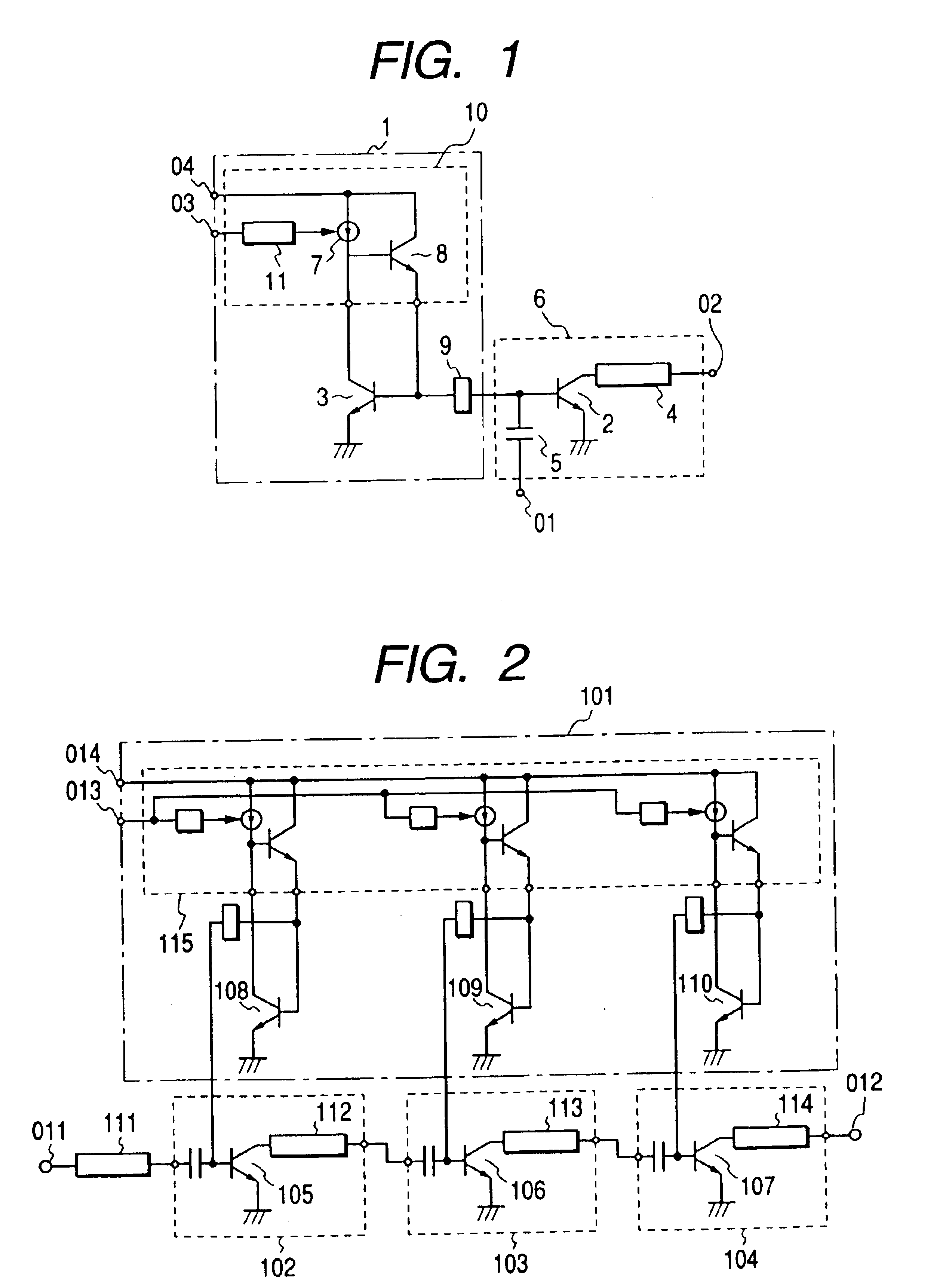
FIG. 1 shows a basic circuit diagram of a power amplifier module as a preferred embodiment of the present invention. Any of the circuit elements in FIG. 1 is a discrete circuit module comprising a single semiconductor integrated circuit or a plurality of semiconductor integrated circuits and an external component connected to it or them. The power amplifier module of first embodiment comprises an amplifier 6 that consists of an output transistor 2, an adjustment circuit 4, and coupling capacitance 5 and an output power control circuit 1 that consists of a V-I logarithmic conversion circuit 11, a constant current source 7, input transistors 3 and 8, and an impedance circuit 9.
The V-I logarithmic conversion circuit 11 executes logarithmic conversion of an input control voltage that is input through a pin 03 into current. This circuit 11 enables that the idling current to flow in the output transistor 2 behaves to exponentially change, relative to the input control voltage. The transis...
second embodiment
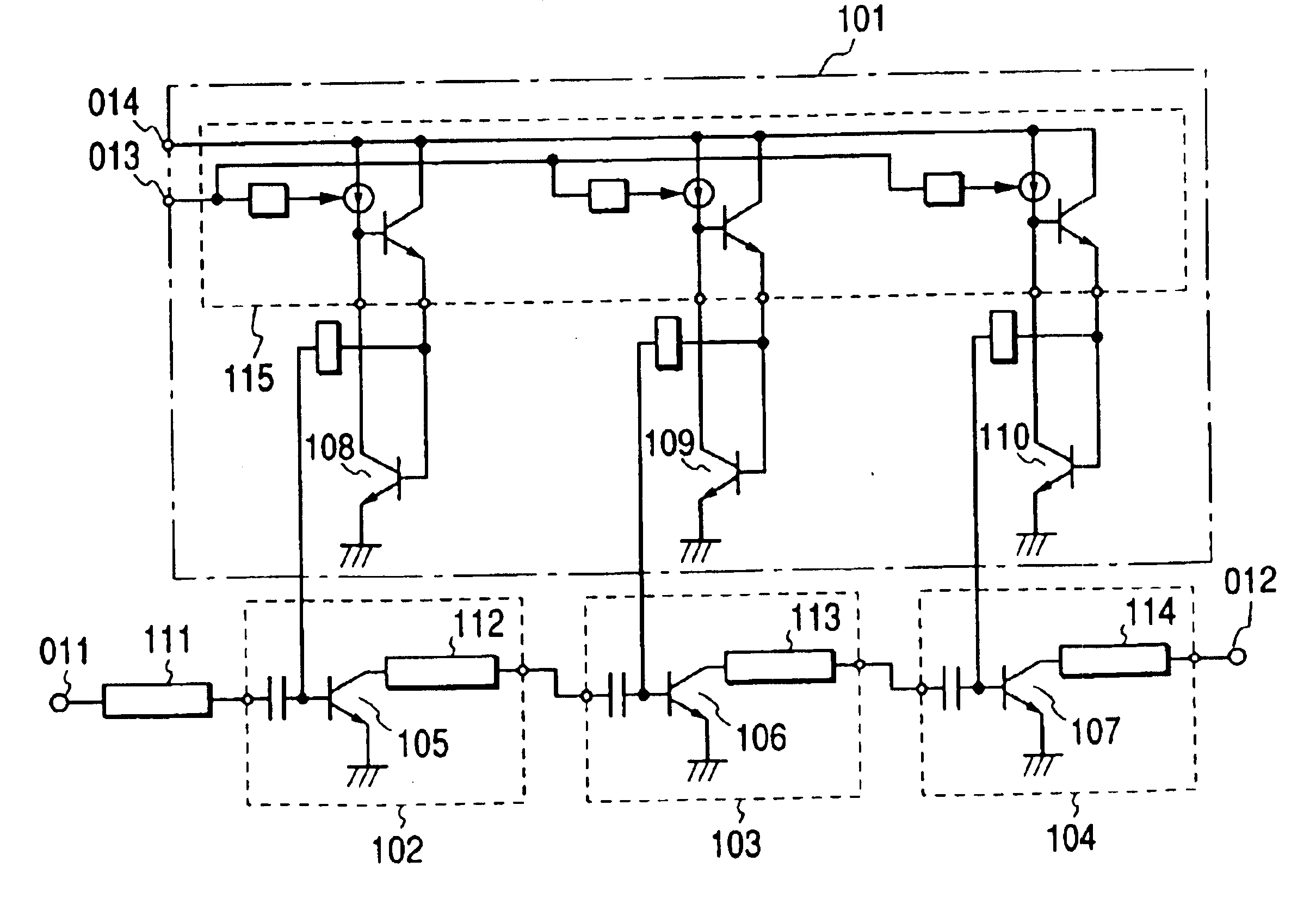
FIG. 2 shows a circuit diagram of a power amplifier module as another preferred embodiment of the present invention. This second embodiment module comprises three stages of power amplifiers connected in tandem. This configuration of the power amplifier module may comprise two stages for systems of relatively small output power requirement, for example, such as a Code Division Multiple Access (CDMA) system.
Unlike the above-mentioned conventional multi-stage amplifier module shown in FIG. 9, three stages of amplifiers of second embodiment are supplied with the reference current that determines the idling current to flow through the transistors in the stages from an output power control circuit 101 that executes control operation by same means. The idling currents flowing across transistors 105, 106, and 107 for amplification (corresponding to the above-mentioned transistor 2) in amplifiers 102, 103, and 104 are as large as mirror ratio times the currents flowing across current-sensing...
third embodiment
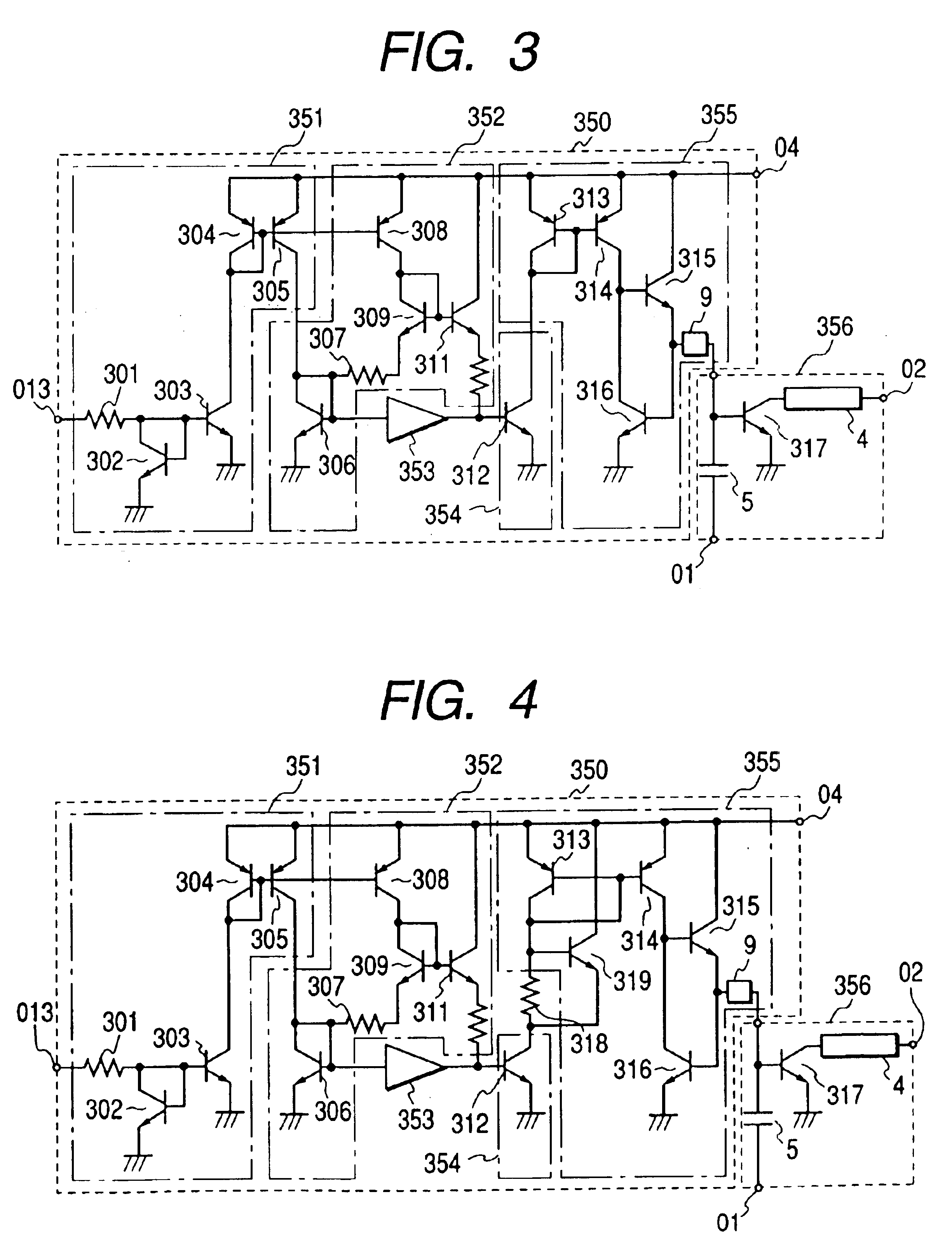
For example, increasing the resistance of the resistor 307 causes control sensitivity to increase because the voltage across the resistor 307 rises; inversely, decreasing the resistance causes control sensitivity to decrease. This means that control sensitivity can be determined by properly selecting a value of the .alpha. coefficient. The a coefficient primarily depends on the relative ratio of the resistance of the resistor 307 to the resistance of the resistor 301. Thus, the value of .alpha. is substantially constant, regardless of the productive deviation of the resistors. In other words, the control circuit of third embodiment has control sensitivity that is not susceptible to productive deviation, provided its circuit elements are packaged on a single semiconductor integrated circuit.
The voltage occurred across the resistor 307 is conducted via level-shift transistors 309 and 311 to the base of a transistor 312 where it is converted into a collector current of the transistor 3...
PUM
 Abstract
Description
Claims
Application Information
 - R&D
- Intellectual Property
- Life Sciences
- Materials
- Tech Scout
- Unparalleled Data Quality
- Higher Quality Content
- 60% Fewer Hallucinations
Browse by: Latest US Patents, China's latest patents, Technical Efficacy Thesaurus, Application Domain, Technology Topic, Popular Technical Reports.
© 2025 PatSnap. All rights reserved.Legal|Privacy policy|Modern Slavery Act Transparency Statement|Sitemap|About US| Contact US: help@patsnap.com


