Micro-gap gas filled dielectric capacitor

a dielectric capacitor and gas filling technology, applied in the field of capacitors, can solve the problems of increasing the difficulty of component quality maintenance, the limited frequency spectrum of capacitors in particular, and the significant challenges of component designers for generating and processing signals in the millimeter wave spectrum, and achieve the effect of improving performan

Inactive Publication Date: 2004-08-10
MIND FUSION LLC
View PDF6 Cites 17 Cited by
  • Summary
  • Abstract
  • Description
  • Claims
  • Application Information

AI Technical Summary

Benefits of technology

A capacitor is provided for high frequency applications. The capacitor utilizes either a vacuum or gas dielectric to provide an improved performance. First and second planer electrodes are separated by micro particles having a diameter in the 3-20 micron range. The micro particles are included in an adhesive spread along the peripheral edges of the planer electrodes. The adhesive bonds the separated electrodes together producing a gas or vacuum dielectric between the electrodes.

Problems solved by technology

Circuits for generating and processing signals in the millimeter wave spectrum present significant challenges to component designers.
As the frequencies increase, the quality of the components becomes increasingly difficult to maintain.
Thus, capacitors in particular have a practical upper frequency spectrum at UHF to SHF limitation when they are constructed with conventional dielectric materials.
Consequently, the use of air or a vacuum as a dielectric has not seen widespread use outside of this limited application.
An additional difficulty in using capacitors of a conventional design at millimeter wave frequencies is that most of these capacitors have a lead wire length, or end cap attachment, which would introduce significant circuit inductance as well as series circuit resistance with the capacitor.
These connection techniques also introduce the disadvantageous series inductance and resistance.

Method used


Image

  • Micro-gap gas filled dielectric capacitor
  • Micro-gap gas filled dielectric capacitor
  • Micro-gap gas filled dielectric capacitor

Examples


Embodiment Construction

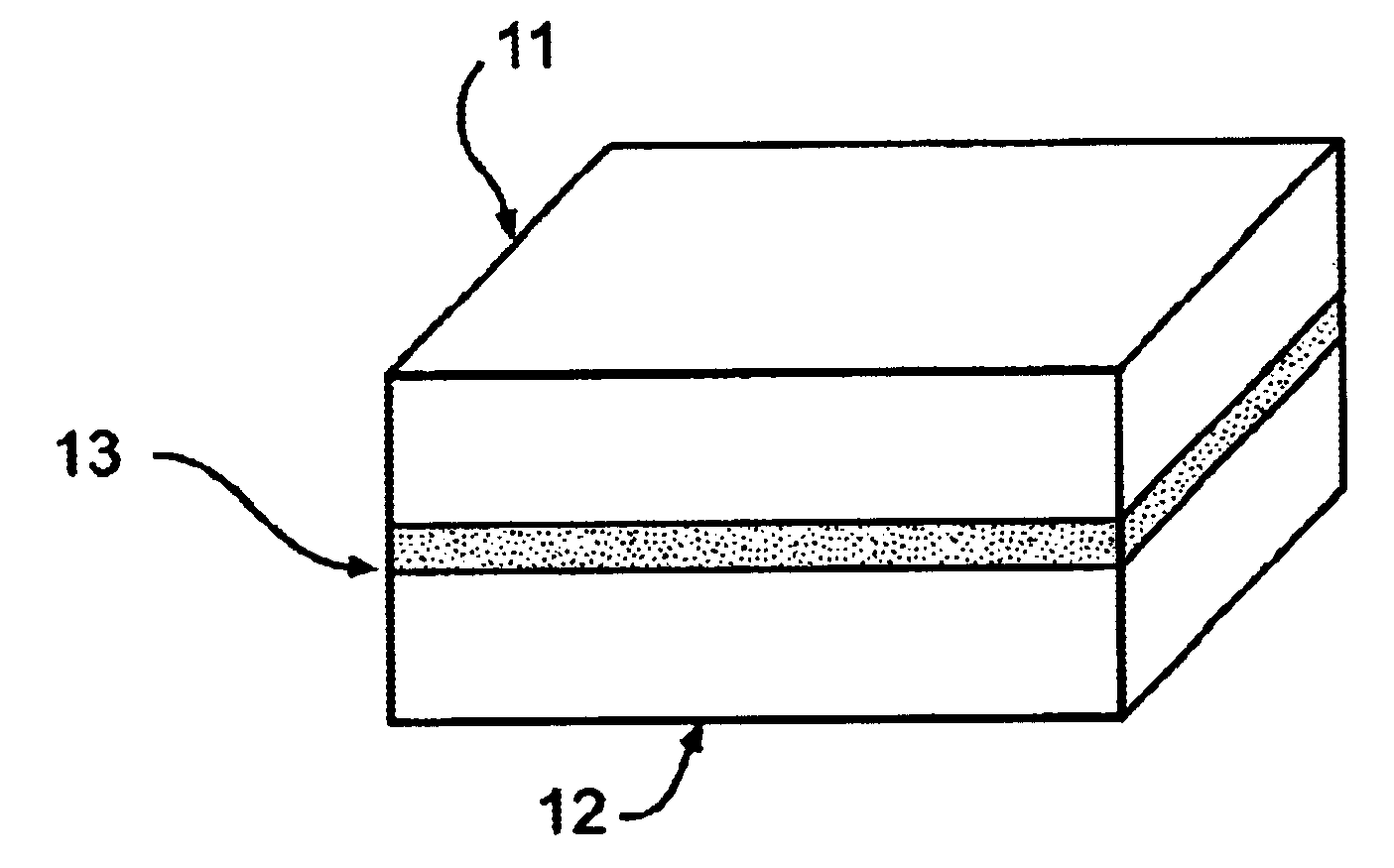
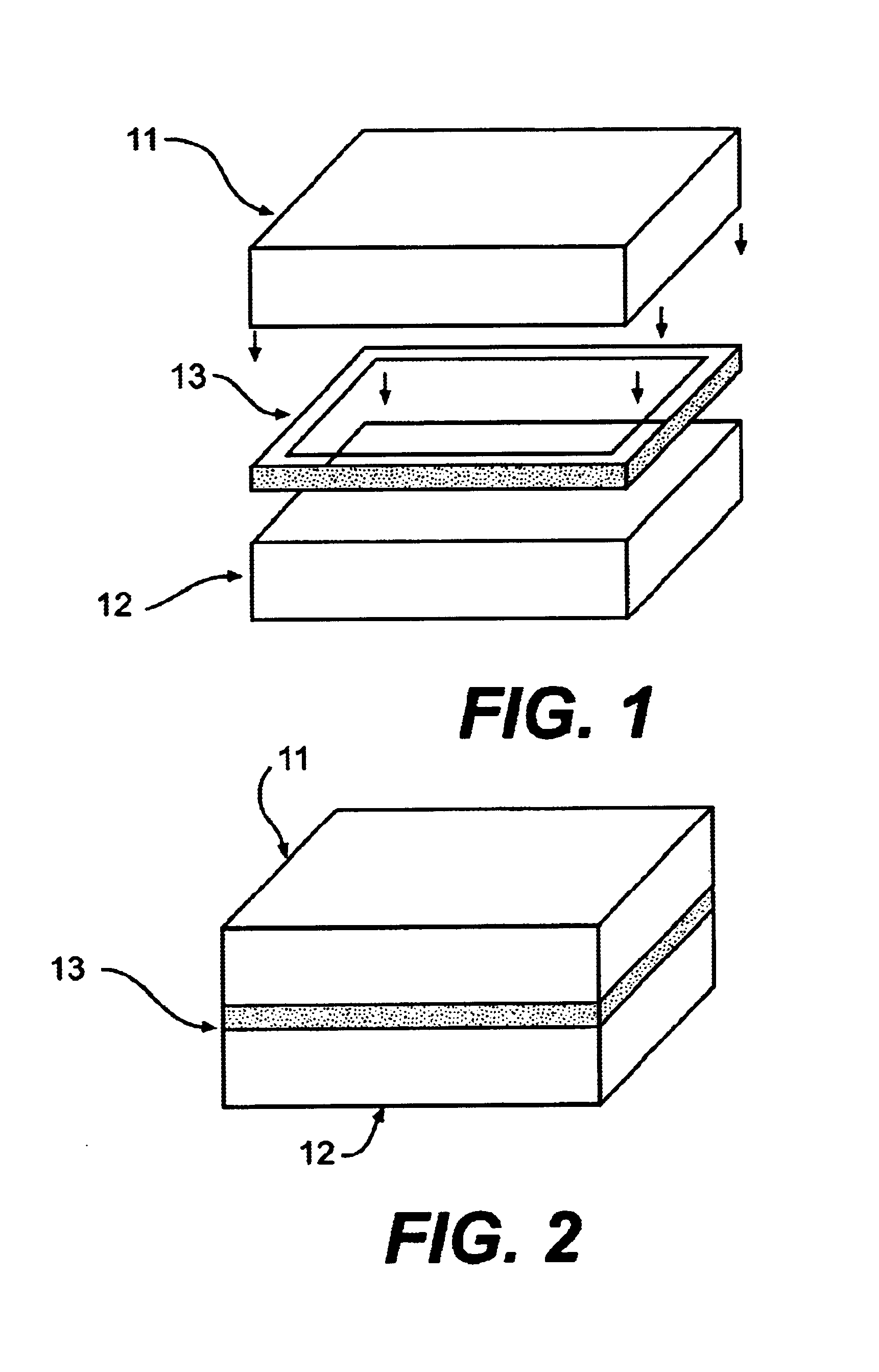
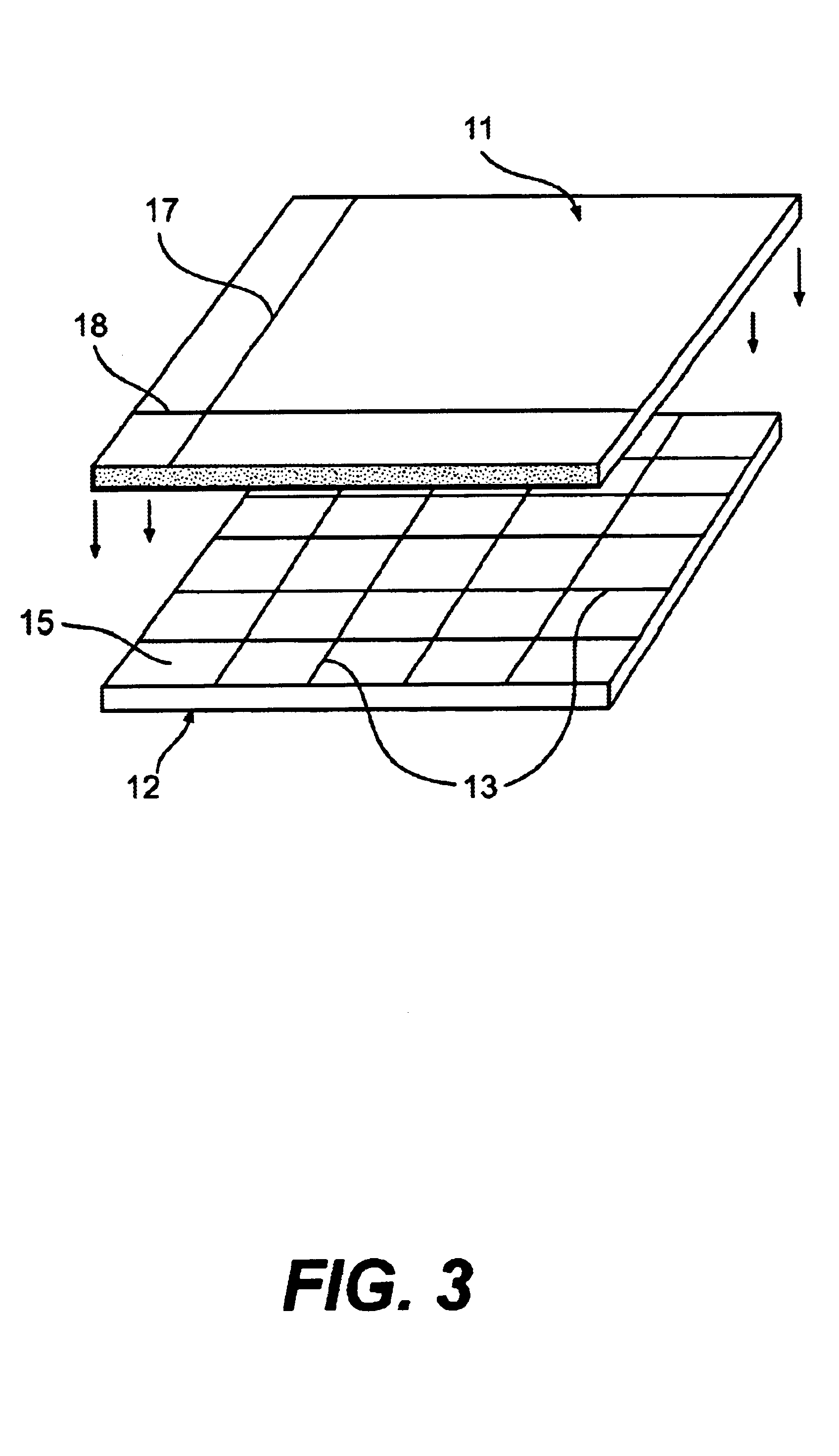
The fundamental formula for a capacitor having 2 planer parallel plates separated by a dielectric material is summarized as:

C=0.0885.epsilon.A / d;

Where C is the capacitance in picofarads (pF);

.epsilon. is the dielectric constant;

A is the area common to both plates; and

d is the distance between the plates in centimeters.

In practice, the dielectric constant .epsilon. is determined by the material between the electrodes of the capacitor. Many common dielectric materials used in capacitors designed for lower frequency operations exhibit a significant change in dielectric constant .epsilon. as well as higher losses as the frequency increases. At low frequencies, having a dielectric with a high dielectric constant produces a greater capacity for the size of the component. At higher frequencies, the internal equivalent series resistance (ESR) and lead inductance losses increase as frequencies increases degrading the component quality.

Air has a dielectric constant of 1 which is substantially...


PUM


Abstract

The gas dielectric capacitor for high frequency applications. The capacitor has first and second planner electrodes separated by an adhesive having solid particles, which establish the distance between electrodes. An adhesive is formed along peripheral edges of the planner electrodes. The capacitor may include air, vacuum, or any number of other dielectric gases, which may be under pressure. A method is disclosed for manufacturing an array of capacitors having a pressurized gas dielectric.

Description

The present invention relates to components used in high frequency / microwave circuit applications. Specifically, a single layer gas filled or vacuum capacitor is described for use in millimeter wave applications having a stable capacitance with low radio, frequency signal losses.Radio communication services are becoming so numerous they are reaching the 50 GHz millimeter wave spectrum. As the demand for more telecommunications services increases, and the spectrum becomes increasingly crowded, it is foreseeable that applications in the 50-100 GHz millimeter wave spectrums will be utilized for various telecommunications applications.Circuits for generating and processing signals in the millimeter wave spectrum present significant challenges to component designers. As the frequencies increase, the quality of the components becomes increasingly difficult to maintain. Specifically, for a basic capacitor utilized in circuits operating at these frequencies, the internal equivalent series r...

Claims


Application Information

Patent Timeline
Patent Type & Authority Patents(United States)
IPC IPC(8): H01G4/30H01G4/018H01G4/02H01G
CPCH01G4/02
Inventor CHEUNG, WILLIAM S H
Owner MIND FUSION LLC
Why Eureka
Try Eureka