
Electro luminescent element

a luminescent element and electroluminescent technology, applied in the direction of discharge tube luminescnet screen, other domestic articles, natural mineral layered products, etc., can solve the problems of high crystallinity and low heat endurance, the majority of these materials cannot be used as materials, and the crystallinity is high

Inactive Publication Date: 2004-08-17
TOYOTA CENT RES & DEV LAB INC
View PDF10 Cites 21 Cited by
  • Summary
  • Abstract
  • Description
  • Claims
  • Application Information

AI Technical Summary

Problems solved by technology

However, even though each of the conventional hole transporting, luminescence, and electron transporting molecules have good electric functionality characteristics, they also suffer problems of high crystallinity and low heat endurance.
Because of these disadvantages, most of these materials cannot be used as materials for an organic electro luminescent element.
For example, even though TPD (tetraphenylbenzidin) and triphenylamine are materials with good hole transporting ability, they exhibit high crystallinity and low heat endurance, which causes crystallization leading to element breakdown within one month after forming an element.
Similarly, even though PBD (t-butylbiphenylylphenyloxadiazole) is a material with good electron transporting ability, it has a fast crystallization, leading to an element breakdown within one week of forming a film.

Method used


Image

  • Electro luminescent element
  • Electro luminescent element
  • Electro luminescent element

Examples


example 2

Synthesis of Ditoluidinoadamantane (15)

A mixture of 13 g of 2-adamantanone, 60 g of o-toluidine, and 18 g of o-toluidine hydrochloride was introduced to a flask with a water remover. The mixture was heated and refluxed at 250.degree. C. (oil bath) under nitrogen atmosphere. Sixty hours later, a KOH solution was added so that the pH was approximately 10, and the mixture was extracted with chloroform and washed with water. The mixture was then dried with sodium sulfate, evaporated, and purified with silica gel column chromatography, to obtain 4.2 g of ditoluidinoadamantane as a white solid. ##STR26##

example 3

Synthesis of Didimethylanilinoadamantane (16)

A mixture of 13 g of 2-adamantanone, 63 g of 2,6-dimethylaniline, and 20 g of 2,6-dimethylaniline hydrochloride was introduced to a flask with a water remover. The mixture was heated and refluxed at 250.degree. C. (oil bath) under nitrogen atmosphere. Eighty hours later, a KOH solution was added so that the pH was approximately 10, and the mixture was extracted with chloroform and washed with water. The mixture was then dried with sodium sulfate, evaporated, and purified with silica gel column chromatography, to obtain 6.5 g of didimethylanilinoadamantane as a white solid. ##STR27##

example 4

Synthesis of a Hole Transporting Molecule (17)

A mixture of 252 mg of dianilinoadamantane (compound 14), 1.0 g of iodobenzene, 1.1 g of potassium carbonate, 700 mg of copper powder, 250 mg of CuO, and 5 g of decalin was heated and stirred for 31 hours under nitrogen atmosphere at 170.degree. C. The mixture was then purified by silica gel column chromatography (chloroform-hexane 1:1) to obtain 115 mg of a hole transporting molecule (17). ##STR28##


PUM

PropertyMeasurementUnit
luminanceaaaaaaaaaa
temperatureaaaaaaaaaa
glass transition temperatureaaaaaaaaaa

Abstract

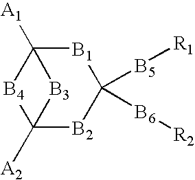
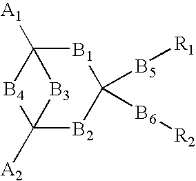
In order to provide an electro luminescent element with high heat endurance and low crystallinity using functional molecules having functions of hole transporting, luminescence, and electron transporting, an electro luminescent element according to the present invention comprises one or more organic compound layers 14 between a first electrode 12 and a second electrode 16, wherein at least one of the organic compound layers 14 is a condensed ring compound derivative represented by the following chemical formula,in which A1 and A2 represent substituents, B1 through B6 represent directly connected or di functional substituents, and R1 and R2 represent functional units having each of the functions of hole transporting, luminescence, and electron transporting, such as triphenylamine, coumarin, and oxadiazole derivative.

Description

1. Field of the InventionThe present invention relates to an electro luminescent element and in particular to improved organic compound materials for use in an electro luminescent element.2. Description of the Related ArtAn electro luminescent element is constructed by layering, in order, a transparent first electrode (such as, for example, an ITO), an organic compound layer with an organic compound having strong fluorescence, and a second electrode formed of a metal (such as, for example, Mg). The organic compound layer is constructed by layering a hole transporting molecule, a luminescence molecule, and an electron transporting molecule in order, and emits light when electric field is applied between the pair of electrodes. In other words, when holes are injected from the first electrode and electrons are injected from the second electrode, the injected holes and electrons move through the organic compound layer and collide with each other to recombine and vanish. By this recombin...

Claims


Application Information

Patent Timeline
Patent Type & Authority Patents(United States)
IPC IPC(8): C09K11/06H05B33/14C07C13/64H10K99/00
CPCC07C13/64C09K11/06H01L51/0058H01L51/006H01L51/0072H05B33/14C09K2211/1007H01L51/0035H01L51/0054H01L51/007H01L51/0081Y10S428/917H10K85/111H10K85/622H10K85/6565H10K85/626H10K85/633H10K85/6572H10K85/324
Inventor TANAKA, HIROMITSUMOURI, MAKOTOTAKEUCHI, HISATOTOKITO, SHIZUO
Owner TOYOTA CENT RES & DEV LAB INC
Learn More