Hybrid-vehicle drive unit

a hybrid vehicle and drive unit technology, applied in the direction of machines/engines, reciprocating combination engines, gearing, etc., can solve the problems of preventing centering precision, and affecting the efficiency of motor-generators. , to achieve the effect of preventing the centering precision of the crank shaft and directly affecting the support position of the rotor

Inactive Publication Date: 2004-08-17
AISIN AW CO LTD +1
View PDF18 Cites 55 Cited by
  • Summary
  • Abstract
  • Description
  • Claims
  • Application Information

AI Technical Summary

Benefits of technology

According to the above aspect of the invention, the motor is separated with the stator fixed to the motor housing and with the rotor rotatably supported by the motor housing, and a predetermined clearance is left between the rotor and the torque converter. Thus, it is possible to provide support with high centering precision without influence by eccentric rotation of the crank shaft. The above-described construction also ensures a clearance (air gap) of high precision by preventing the rotor and the stator from interfering with each other due to expansion or contraction of the torque converter caused by changes in centrifugal hydraulic pressure and so on. Thus, the efficiency of the motor can be enhanced by narrowing (decreasing) the clearance, and the functions as described above can be performed reliably with a relatively compact structure. Further, since the predetermined clearance exists between the rotor and the torque converter, the permanent magnet is prevented from demagnetizing due to generation of heat within the torque converter. Furthermore, since the lock-up clutch and the rotor, which are disposed in the front cover of the torque converter, are located far from each other, trash such as iron powder can be prevented from flaking off the permanent magnet of the rotor and accumulating in the lock-up clutch. Thus, the lock-up clutch can operate without hindrance.
The predetermined clearance between the rotor and the hydraulic power transmission may be 0.8 to 3.5 mm whereby the rotor can be reliably prevented from being pressed by and interfering with the stator due to deformation of the hydraulic power transmission resulting from changes in centrifugal hydraulic pressure and so on. Also, the motor housing and thus the hybrid-vehicle drive unit need not be increased in size. Further, the clearance makes it possible to prevent the permanent magnet from becoming demagnetized due to generation of heat by the torque converter. Furthermore, the clearance makes it possible to prevent trash such as iron powder from flaking off the permanent magnet of the rotor and accumulating in the lock-up clutch disposed in the front cover of the torque converter. As a result, the lock-up clutch can operate without hindrance.

Problems solved by technology

However, vibrations due to combustive explosion cause the crank shaft to rotate eccentrically (with deflection), preventing centering precision.
Further, since the output of the motor-generator increases in proportion to an increase in the axial length of opposing surfaces of the stator and the rotor, the efficiency of the motor-generator is also greatly affected by precision in axial support of the rotor.
Thus, centering precision of the crank shaft directly affects precision of the support position of the rotor.
Also, since the torque converter undergoes deformation such as expansion or contraction due to changes in inlet pressure and centrifugal hydraulic pressure, the stator fixed to the pump impeller and the rotor fixed to the turbine runner are axially displaced relative to each other, and the motor suffers a corresponding decrease in efficiency.
Further, if the motor-generator is directly mounted radially outside of the torque converter as disclosed in Kokai 5-024447, it is difficult to enlarge the diameter of the motor-generator owing to spatial restrictions such as vehicle height.
It is difficult to provide a motor (generator) having the necessary output torque within such a limited space.
Further, since the rotor of the motor-generator is directly supported radially outside of the cover of the torque converter, when the torque converter undergoes deformation, i.e., expansion or contraction due to changes in inlet pressure or centrifugal hydraulic pressure, there is the possibility of interference between the stator and the rotor.
Further, the torque converter generates a great amount of heat.
As a result, iron powder dispersed in hydraulic fluid in the torque converter may accumulate in the lock-up clutch and obstruct operation of the lock-up clutch.

Method used


Image

  • Hybrid-vehicle drive unit
  • Hybrid-vehicle drive unit
  • Hybrid-vehicle drive unit

Examples


Embodiment Construction

A preferred embodiment of the invention will now be described with reference to the drawings.

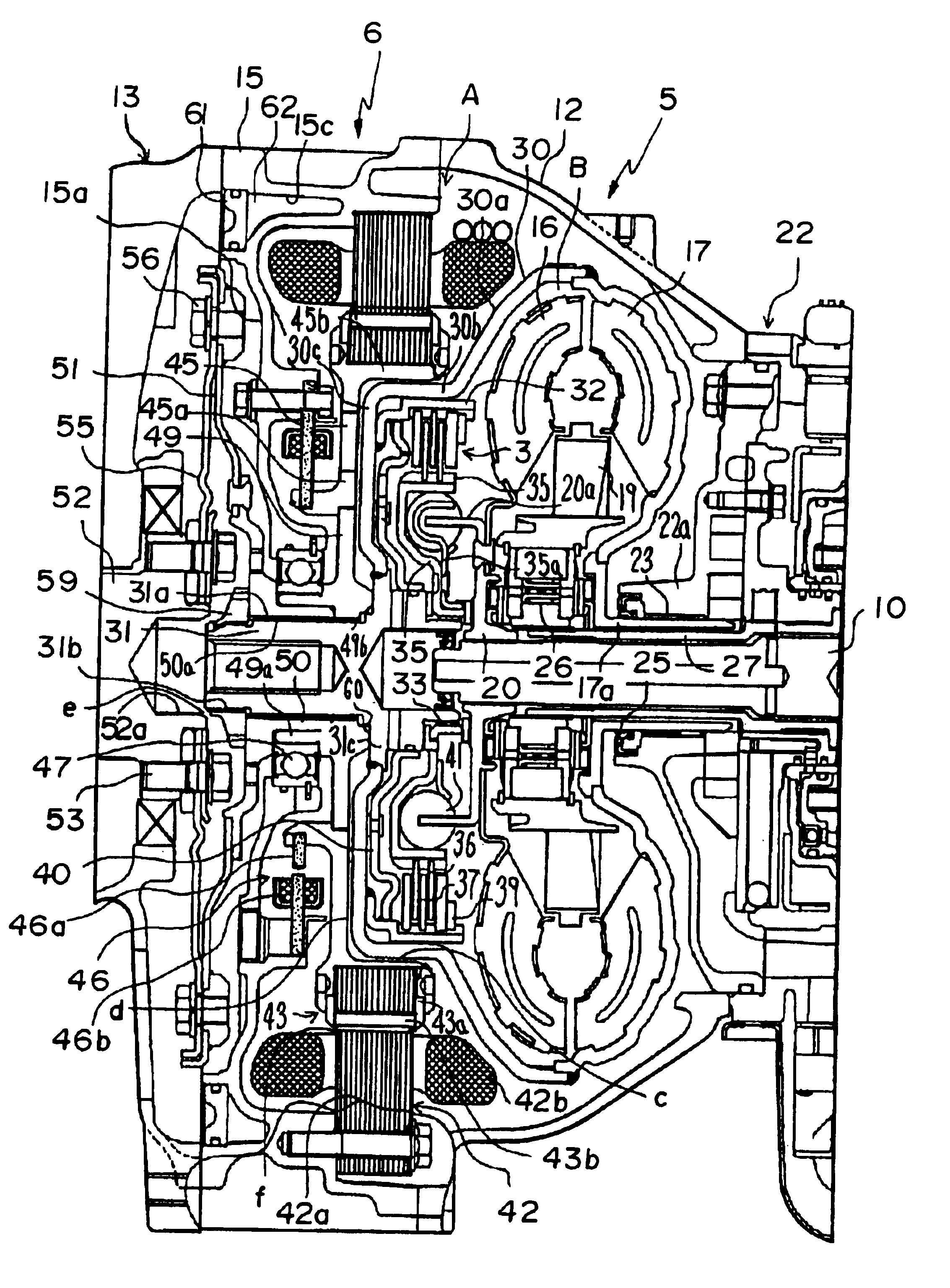
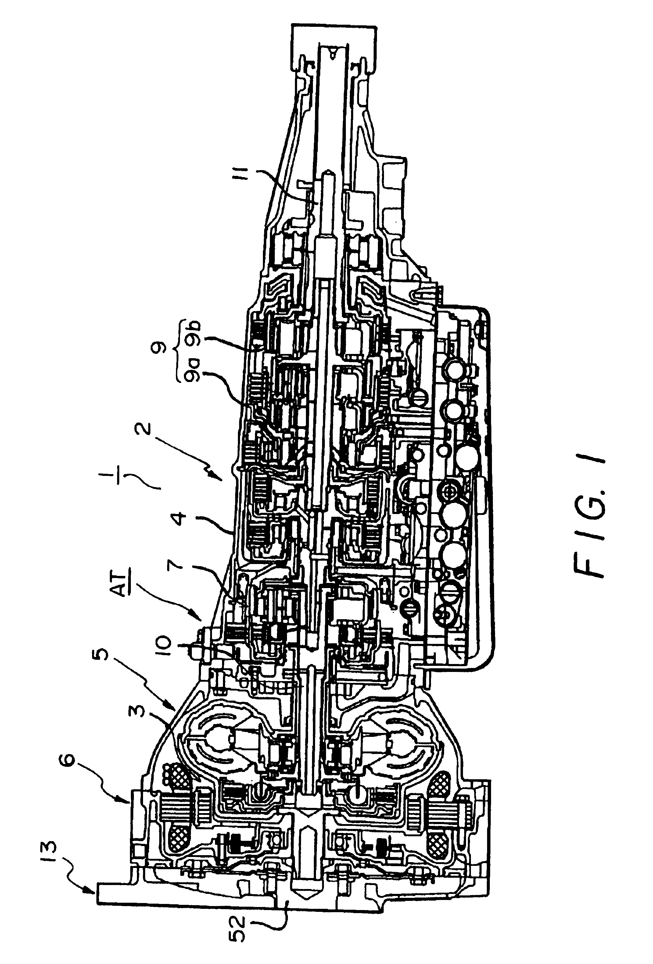
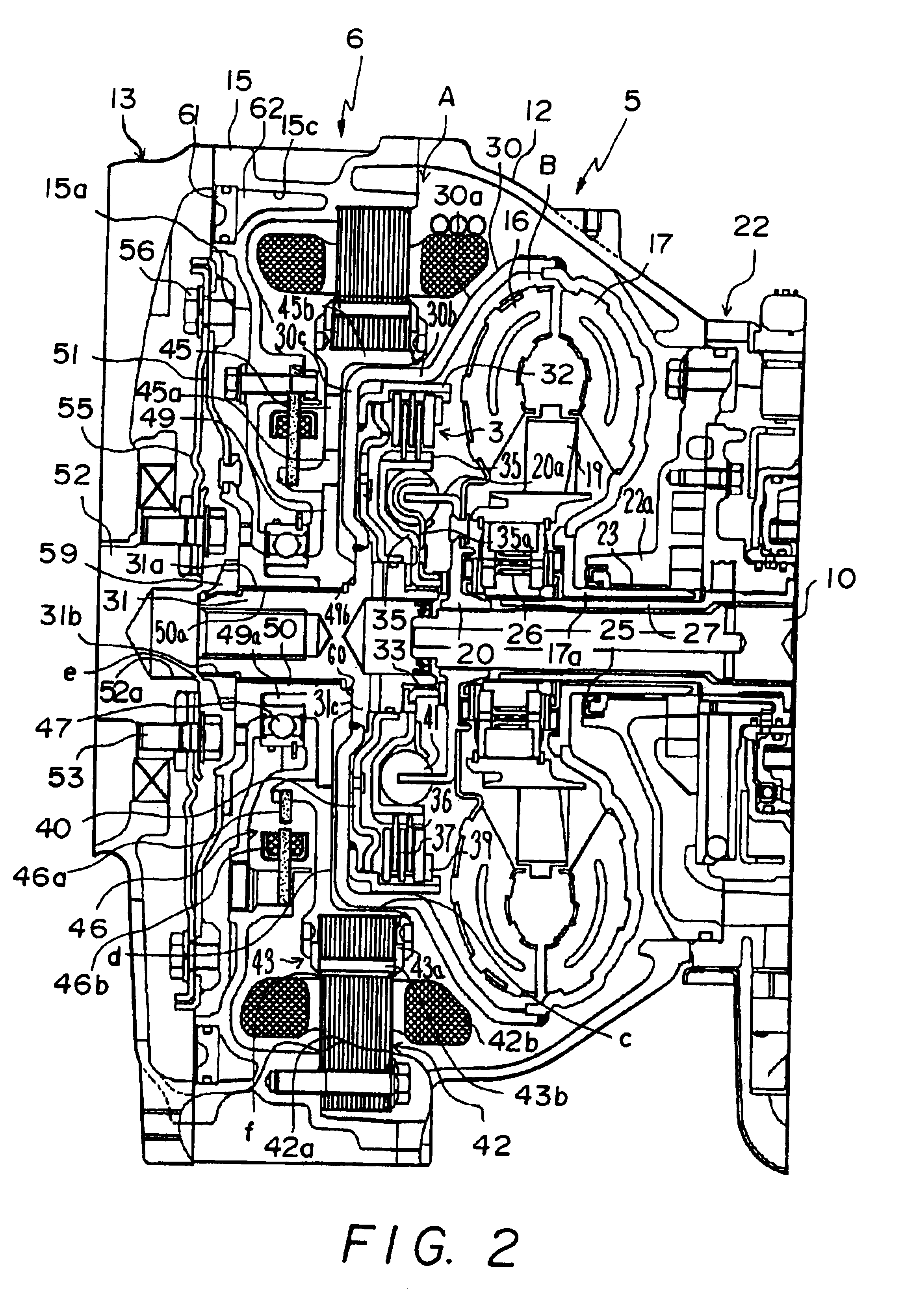
FIG. 1 shows a hybrid-vehicle drive unit 1 as including a multiple-stage transmission 2 housed in a transmission case 4, a torque converter 5 having a lock-up clutch 3, and a motor-generator 6 in the form of a brushless DC motor. At the left-side of FIG. 1, the hybrid-vehicle drive unit 1 is connected with an internal combustion engine 13 such as a gasoline engine. Thus, the hybrid-vehicle drive unit 1 includes a conventional automatic transmission AT with its torque converter, additionally equipped with the motor-generator 6.

The hybrid-vehicle drive unit 1 is arranged in a single-axis manner and is applied to a front-engine rear-drive (FR) type. More specifically, in order from the engine side, the motor-generator 6, the torque converter 5 and the automatic speed-change mechanism 2 are arranged on a single axis. In the automatic speed-change mechanism 2, an over-drive mechanism 7 constructe...


PUM


Abstract

A hybrid-vehicle drive unit supports a motor-generator with high precision, improving the efficiency of the motor-generator, and reducing the size of the motor-generator, independent of any influence of centering precision of the crank shaft and of deformation of the torque converter. According to the invention, a motor housing is disposed between a converter housing and an internal combustion engine, and a bearing is fitted to a lateral wall provided in a front portion of the motor housing. Rotor supporting members are independently supported by the bearing. Eccentric rotation of the crank shaft resulting from explosive vibrations of the engine is counteracted by two flex plates. Owing to a predetermined clearance, one of the rotor supporting members as a separate component is free from the influence of deformation of the torque converter.

Description

INCORPORATION BY REFERENCEThe disclosure of Japanese Patent Application No. 2000-292979 filed on Sep. 26, 2000 is incorporated herein by reference in its entirety.1. Field of the InventionThe invention relates to a drive unit for a parallel-type hybrid vehicle wherein an engine and a motor are coupled for use as a power source, and more particularly to a hybrid-vehicle drive unit wherein a motor is fitted to an automatic transmission having a hydraulic power transmission.2. Description of Related ArtJapanese Patent Application Laid-Open No. ("Kokai") HEI 9-215270, discloses a drive unit for a parallel-type hybrid vehicle wherein a motor-generator is fitted to an automatic transmission equipped with a torque converter. The driving force of the motor-generator assists the driving force of the engine e.g. when the vehicle starts from a standstill or is accelerated. The motor-generator functions as a generator to supplement the effect of the engine brake when the vehicle runs down a slo...

Claims


Application Information

Patent Timeline
Patent Type & Authority Patents(United States)
IPC IPC(8): B60K6/00B60K6/04B60K17/04B60K6/20B60K6/24B60K6/26B60K6/36B60K6/40B60K6/405B60K6/485B60K6/54F16H45/02
CPCB60K6/40B60K6/405B60K6/485B60K6/547F16H2045/021Y10S903/903Y10S903/951Y10S903/905Y10S903/909Y10S903/906Y10S903/917Y10S903/952Y10S903/919Y02T10/6226Y02T10/62
Inventor TSUZUKI, SHIGEOOMOTE, KENJIHASEBE, MASAHIROWAKUTA, SATORUSHINOHARA, KEIICHITABATA, ATSUSHITAGA, YUTAKANAKAMURA, SEIJIAMANO, MASAYA
Owner AISIN AW CO LTD
Why Eureka
Try Eureka