Apparatus for and method of forming multiple simultaneous electronically scanned beams using direct digital synthesis

a technology of electronic scanned beams and apparatuses, applied in direction finders, instruments, antennas, etc., can solve the problem of only producing a single beam

Inactive Publication Date: 2004-08-17
THE GOVERNMENT OF THE UNITED STATES OF AMERICA AS REPRESENTED BY THE SEC OF THE NAVY NAVAL RES LAB WASHINGTON
View PDF1 Cites 37 Cited by
  • Summary
  • Abstract
  • Description
  • Claims
  • Application Information

AI Technical Summary

Benefits of technology

Accordingly, a principal object of the present invention is to configure an apparatus and create a method that efficiently and optimally produces multiple simultaneous RF beams, i.e., M beams, each of which can have a different frequency and separate modulation, are independently electronically scanned and can be easily defined in software.
A corollary of the above object is to reduce the number of DDS circuits needed from N.times.M to N, while maintaining the effective aperture size used to generate each of the M independently pointed beams which may contain independent frequency and / or modulation information.
A further object of the present invention is to reduce the need for RF combining circuits in order to generate the multiple simultaneous RF beams.
Another object of the present invention is to generate additional RF beams, which can be used to transmit radar, communications, or other information with a minimal increase in hardware.
Yet still another object of the present invention is to improve the capacity to generate additional RF beams by defining in software the number, frequency, and modulation of the RF beams thereby providing further improvement in system flexibility.

Problems solved by technology

The limitation of the architecture of the prior art is that it produces only a single beam per beamformer and array, using the N elements.

Method used


Image

  • Apparatus for and method of forming multiple simultaneous electronically scanned beams using direct digital synthesis
  • Apparatus for and method of forming multiple simultaneous electronically scanned beams using direct digital synthesis
  • Apparatus for and method of forming multiple simultaneous electronically scanned beams using direct digital synthesis

Examples


example 1

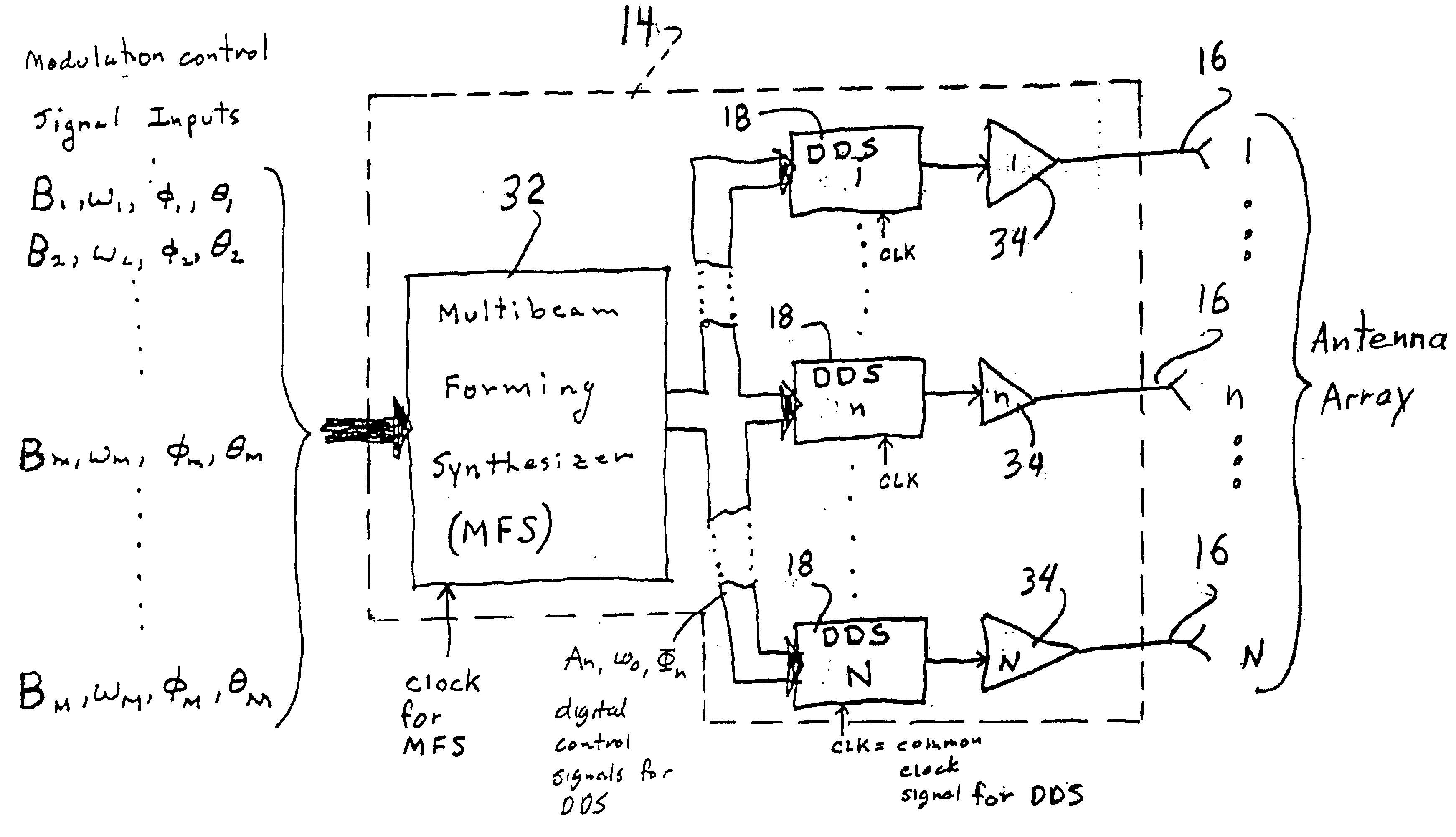
There are a number of ways to implement the digital processing functions of the multibeam forming synthesizer 32 of the present invention. For example, any of the serial or parallel processing methods currently employed in commercially available digital computers would be sufficient. Serial processing computers can perform the processing algorithms sequentially and then distribute the results in serial fashion to each of the 1-N DDSs 18. Parallel processing can be implemented by using a single processor at each one of the 1-N of DDSs 18 to implement the digital calculations for each DDS 16 in parallel. Various configurations that combine both serial and parallel processing can also be implemented. Those skilled in the art recognize that parallel processing provides a processing speed advantage for calculations that can be implemented in parallel (compared to serial processing), thus providing improved and streamlined digital processing.

example 2

Another embodiment for the multibeam forming synthesizer 32 is to implement the digital processing functions in re-configurable logic, such as, for example, a field programmable gate array (FPGA). Such FPGAs can perform software programmable executions of hardware logic, and therefore can be reconfigured to optimize the processing algorithm, based on, for example, the number of beams, type of modulations etc. Such an embodiment provides added flexibility in the capacity of the present invention to be programmed in software.

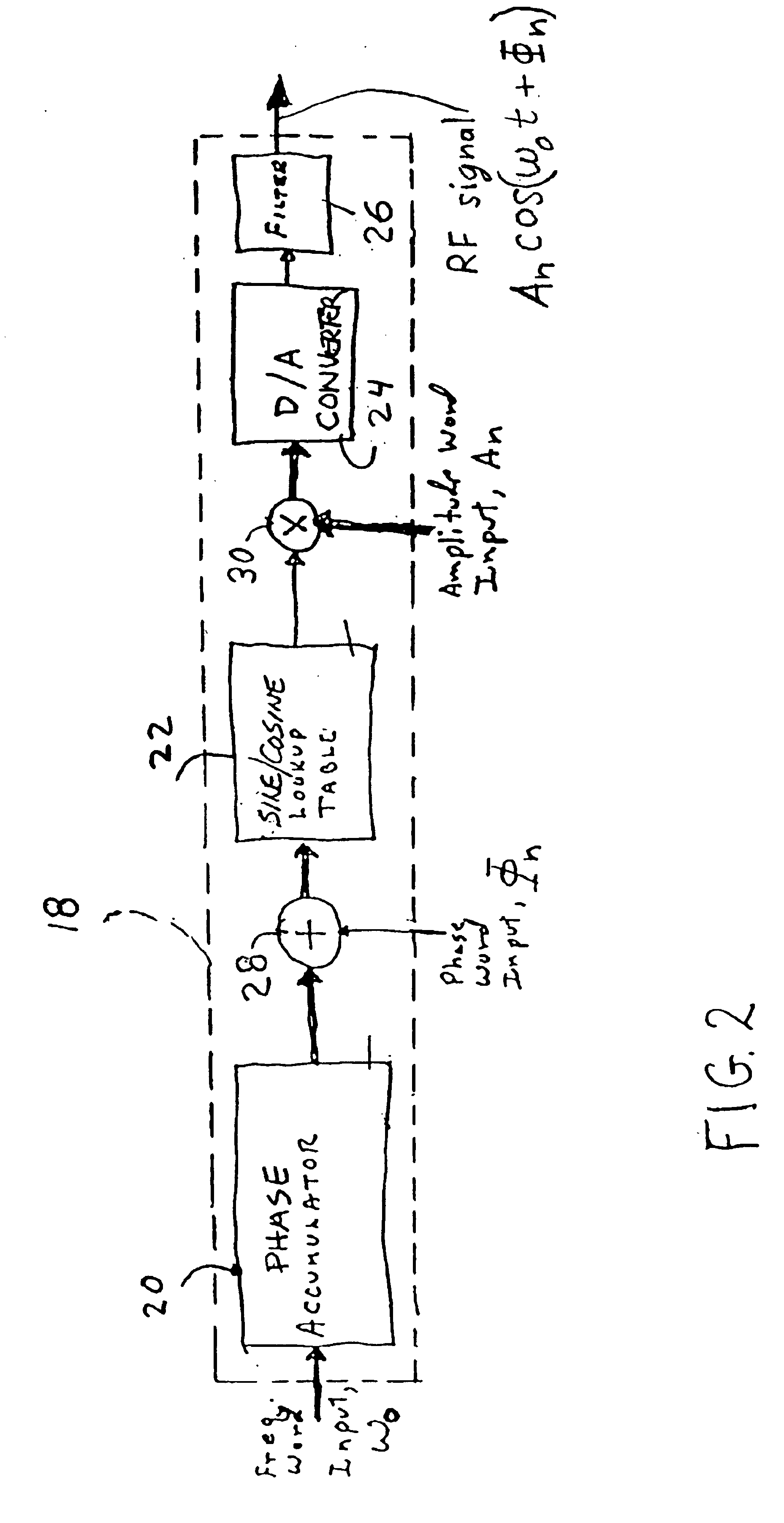
Following each DDS 16 is an amplifier 34 having a bandwidth suitable to amplify and pass the RF signal generated by the DDS 16. Those skilled in the art are aware that the use of the amplifier 34 and bandpass filters 24 of FIG. 2 is optional and dependent upon the desired amount of energy and spectral purity of the signal to be radiated by the antenna array.

example 3

The carrier offset frequency, .omega..sub.o, is computed by the multi-beam forming synthesizer 32 for 1-M beams and can be chosen in many different ways. For example, it could be selected as the mean of the input signal frequencies given by the equation ##EQU1##

For those skilled in the art it is obvious that .omega..sub.o could be selected, for example, at the lower or upper frequency band edges of the composite signal to be formed by the DDS 16. In fact, the only practical restriction on .omega..sub.o is that it must be selected so that it is a valid frequency control word over the usable frequency of operation for the DDS 18.


PUM


Abstract

The apparatus / method according to the present invention accomplishes a reduction in the total number of direct digital synthesizers (DDSs) needed for use in electronically scanned antenna array to generate multiple simultaneous radio frequency (RF) beams. The apparatus includes, inter alia, a multi-beam forming synthesizer, a plurality of DDSs, a corresponding plurality of amplifiers all operatively connected to a plurality of radiating elements of the antenna array. This arrangement uses a single DDS per radiating element. Each DDS uses a composite amplitude, phase and frequency information computed by the multi-beam forming synthesizer to create the proper waveform for driving the antenna array, and accordingly, generating the desired multiple simultaneous RF beams, i.e. 1-M (e.g. 1 through M) RF beams each of which can have a different frequency and separate modulation.

Description

1. Field of the InventionThe present invention relates to an improved apparatus (hardware arrangement) and algorithm that employs a direct digital radio frequency synthesizer to generate and transmit multiple simultaneous radio frequency (RF) beams, which can be electronically scanned.2. Description of the Prior ArtIn the past, a number of methods and apparatus have been used to generate electronically scanned radio frequency beams using array elements. These methods include both analog beamforming and digital beamforming techniques that are applied to transmit array antennas as discussed in the references [1,2]. By the principal of superposition it is possible to apply same frequency signals to each of N radiating elements so that the summation of same frequency signals at a point in the field of the elements forms a single beam, which can be electronically scanned by introducing a relative timing or phase delay at each of the elements. Those skilled in the art know that for exampl...

Claims


Application Information

Patent Timeline
Patent Type & Authority Patents(United States)
IPC IPC(8): H01Q3/26H01Q25/00
CPCH01Q3/26H01Q25/00
Inventor PURDY, DANIEL S.SWINFORD, H. WADE
Owner THE GOVERNMENT OF THE UNITED STATES OF AMERICA AS REPRESENTED BY THE SEC OF THE NAVY NAVAL RES LAB WASHINGTON
Why Eureka
Try Eureka