Control of polarisation of vertical cavity surface emitting lasers

a technology of lasers and cavity surfaces, which is applied in the direction of lasers, optical resonator shapes and construction, semiconductor lasers, etc., can solve the problems of reducing the circular symmetry of the beam of light generated by the vcsel, adding complexity to the structure of the vcsel, and more complicated semiconductor structures

Inactive Publication Date: 2004-08-31
QINETIQ LTD
View PDF14 Cites 36 Cited by
  • Summary
  • Abstract
  • Description
  • Claims
  • Application Information

AI Technical Summary

Problems solved by technology

This approach is used in JP10223973 and EP772269 and results in a more complicated semiconductor structure which can reduce the circular symmetry of the beam of light generated by the VCSEL.
However, this straining of the semiconductor material adds complexity to the structure of the VCSEL.
Furthermore, the strained layer must be relatively thin and such thin layers are difficult to reproduce accurately in bulk manufacture, resulting in VCSELs whose properties are not very reproducible.
However, the inclined structure of the VCSELs complicates the fabrication process used to form the individual VCSEL

Method used


Image

  • Control of polarisation of vertical cavity surface emitting lasers
  • Control of polarisation of vertical cavity surface emitting lasers
  • Control of polarisation of vertical cavity surface emitting lasers

Examples


first embodiment

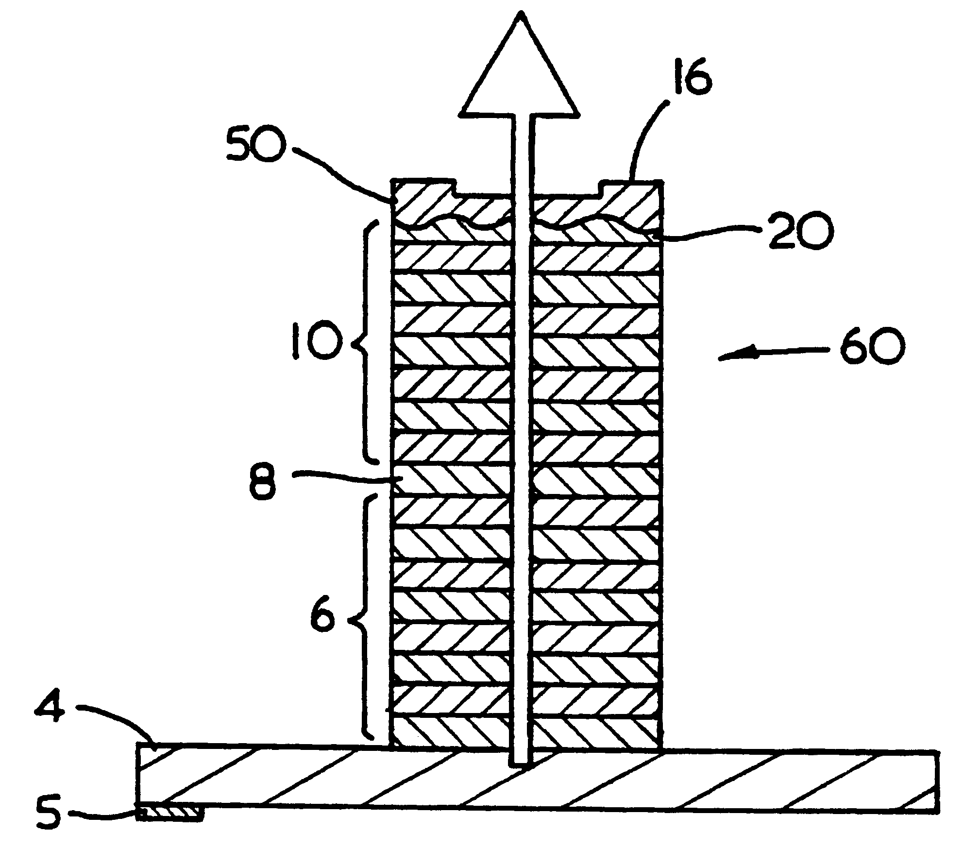
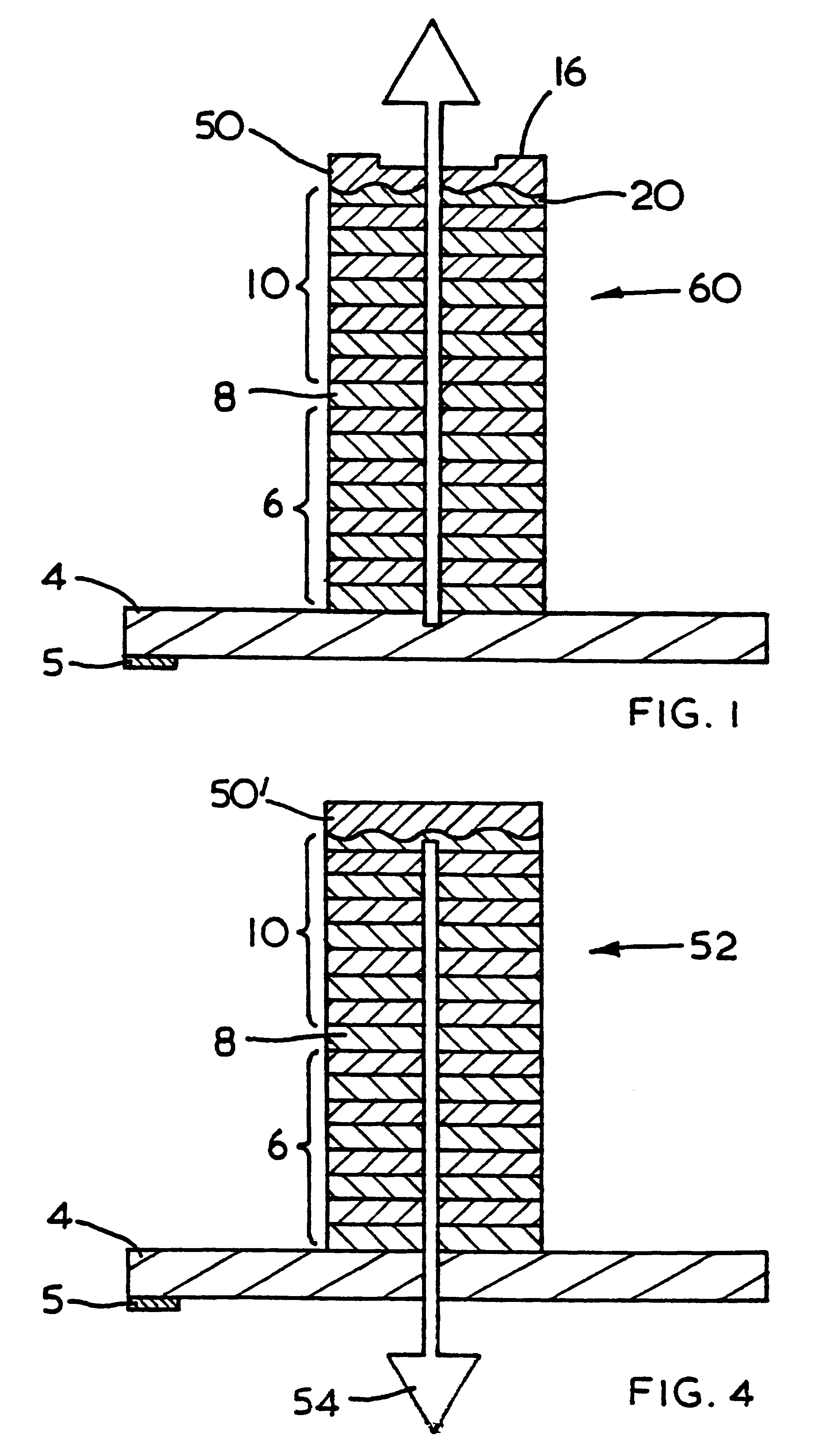
FIG. 1 shows an embodiment of a polarising VCSEL (60) according to the present invention. The VCSEL (60) is grown on a substrate (4) which includes the bottom electrical contact (5) of the VCSEL and comprises a lower multi-layer Bragg stack or mirror (6), a gain region (8) and an upper multi-layer Bragg stack or mirror (10). The upper Bragg mirror (10) is partially reflecting and so light is emitted from the VCSEL (60) from its upper surface. On the upper surface is formed the top electrical contact of the VCSEL which is in the form of a corrugated metal mirror (50) surrounded by an annular region (16). As is well known in the art the gain region (8) consists of quantum wells. Normally the thickness of each layer in each of the Bragg stacks (6,10) are one quarter of the operating wavelength in the semiconductor material (i.e. the wavelength in air divided by four times the refractive index of the Bragg layer).

The substrate (4) is composed of Gallium Arsenide (GaAs) and the layers of...

second embodiment

The second embodiment shown in FIGS. 7 and 8 comprises a VCSEL (90) with like parts identified by the same numerals as in FIGS. 1, 4 and 6. The VCSEL (90), the top part of which is shown in FIG. 7 comprises an upper Bragg stack (10) with a diffraction grating (92) formed on or alternatively in its upper surface. The reflecting properties of the grating (92) are demonstrated schematically in FIG. 8. Part of an incident beam of light (94) from the Bragg stack (10) (shown in dotted lines in FIG. 8) is reflected by the upper surface of the grating (92) to produce a beam (96) which propagates back into the Bragg stack (10). However, the upper surface of the grating (92) is suitably corrugated so that part of the incident beam (94) is diffracted at the interface between the upper surface of the grating (92) and the air above it into a waveguide mode in the layer of grating as shown by light beams (100,102). The light beams (100,102) in the waveguide mode can also diffract from the interfa...


PUM


Abstract

A vertical cavity surface emitting laser (VCSEL) comprising a one dimensional grating structure configured to act as a waveguide, preferably located at an end surface of the VCSEL, for selectively reflecting more of a first polarisation of light back into the cavity of the VCSEL than a second orthogonal polarisation of light. Preferably the VCSEL comprises an upper Bragg mirror, a gain region, and a lower Bragg mirror, and the one dimensional grating structure is located on a top layer of the upper Bragg mirror and the top layer of the upper Bragg mirror has a thickness such that the reflected light of one polarisation constructively interferes with light of said one polarisation which is reflected by the upper Bragg mirror. The VCSEL will then lase at the polarisation which is more predominantly reflected by the grating structure.

Description

1. Field of the InventionThe present invention relates to the control of the polarisation of light emitted by Vertical Cavity Surface Emitting Lasers or VCSELs.2. Discussion of Prior ArtRecently there has been increased interest in VCSELs because they have several potential advantages over conventional edge emitting semiconductor lasers, such as planar construction, the emission of light perpendicular to the surface of the semiconductor substrate and the possibility of fabrication in an array. Edge emitting lasers have the advantage of emitting polarised light, however they emit an elliptical beam of polarised light which requires the use of a lens to couple the elliptical beam to a circular optical fibre. By comparison VCSELs which in their simplest form have a semiconductor structure which is axially symmetric about the vertical axis of the VCSEL will emit a circular beam of light which is unpolarised. A circular beam can be directly coupled into a circular optical fibre without t...

Claims


Application Information

Patent Timeline
IPC IPC(8): H01S5/00H01S5/183
CPCH01S5/18355H01S5/18386
Inventor AMOS, RICHARD MLEWIS, MEIRION FWILSON, REBECCA A
Owner QINETIQ LTD
Why Eureka
Try Eureka