
Stereolithographic method for combining components of varying densities

a stereolithography and component technology, applied in the field of stereolithography, can solve the problems of difficult to achieve the desired accuracy, time-consuming and labor-intensive, and the cost of producing solid models by stereolithography is as high as traditional manufacture, and the model made by traditional machining methods tend to be extremely expensiv

Inactive Publication Date: 2004-09-14
BAE SYSTEMS PLC
View PDF16 Cites 33 Cited by
  • Summary
  • Abstract
  • Description
  • Claims
  • Application Information

AI Technical Summary

Benefits of technology

The invention aims to provide a method for producing a stereolithographic article with a solid part that can be accurately drilled and attached to wind tunnel stands or other articles without compromising the strength of the article. The method allows for the production of articles with a less dense region and a denser, solid region without the need for separate components that have to be bonded together using an adhesive resin. This results in an article with no weak bond lines that could affect its structural performance.

Problems solved by technology

Such models made by traditional machining methods tend to be extremely expensive and it is hard to achieve the desired accuracy.
However, producing solid models by stereolithography is time consuming and is as expensive as traditional manufacture due to the high price of the resin.
However, quickcast articles cannot be drilled to allow attachment to wind tunnel stands or other articles.
The material may shatter if an attempt is made to drill into it or to machine it.
No satisfactory method of providing a quickcast model with a solid part suitable for accurate drilling and attachment has hitherto been devised.
In the case of models for wind tunnels, any models being made from several components bonded together are not of a sufficient strength to withstand the rigours of wind tunnel testing.
They may bend at the bond line, so distorting the shape of the model under test, or may actually break at these weaker points.
This structural behaviour is clearly unacceptable in any applications where the stereolithographic articles will face high stresses.

Method used


Image

  • Stereolithographic method for combining components of varying densities
  • Stereolithographic method for combining components of varying densities
  • Stereolithographic method for combining components of varying densities

Examples


Embodiment Construction

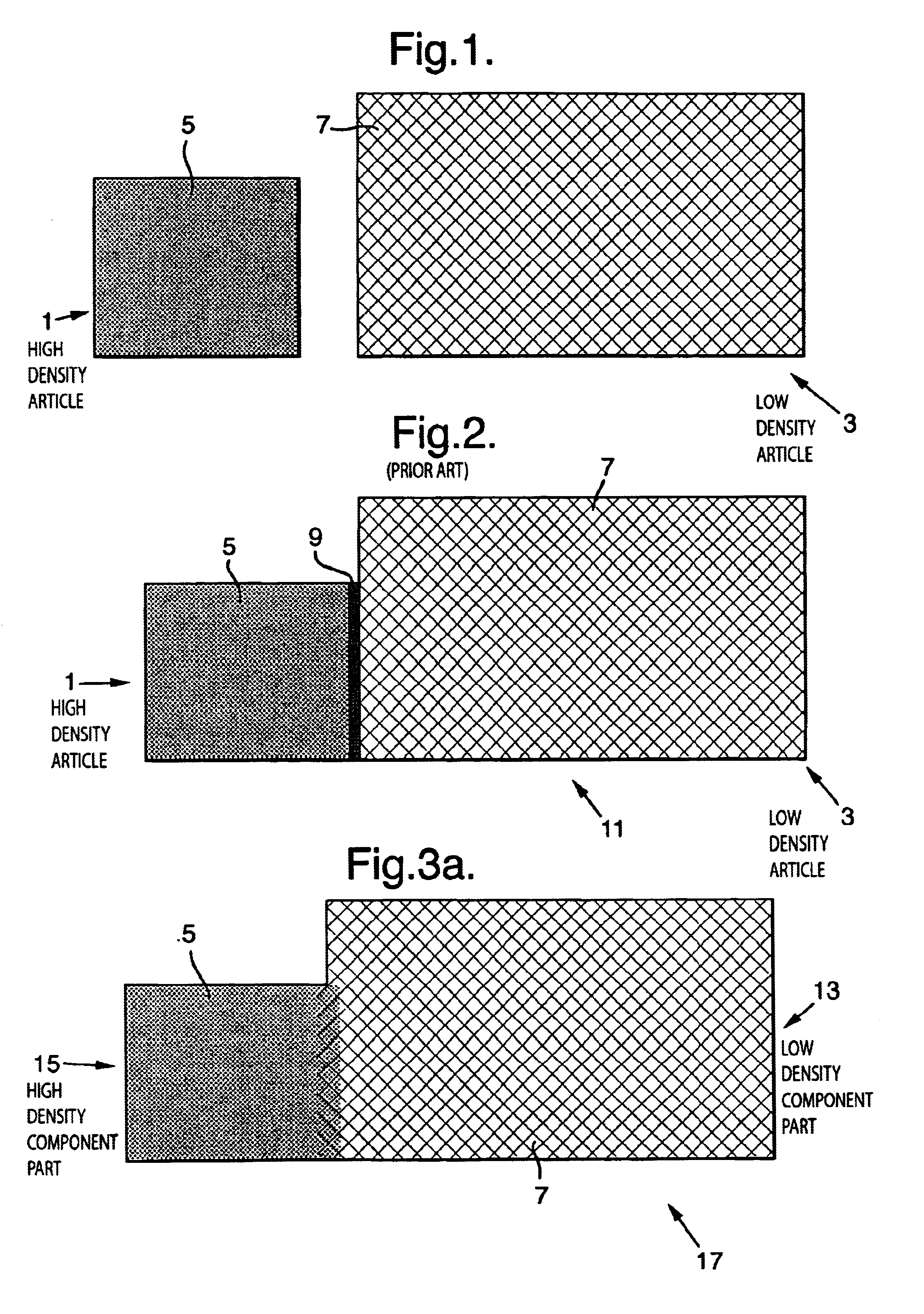
FIG. 1 shows a high density article 1 having a solid internal structure 5 and also a low density quickcast article 3 having a honeycomb-like internal structure 7.

FIG. 2 shows articles 1 and 3 joined together in the traditional manner to form article 11. The articles 1 and 3 are bonded together using a cured resin adhesive 9. Where the articles 1 and 3 are joined, the resin adhesive 9 gives rise to a bond line which is weaker than the adjacent structures 5 and 7, so reducing the strength of article 11.

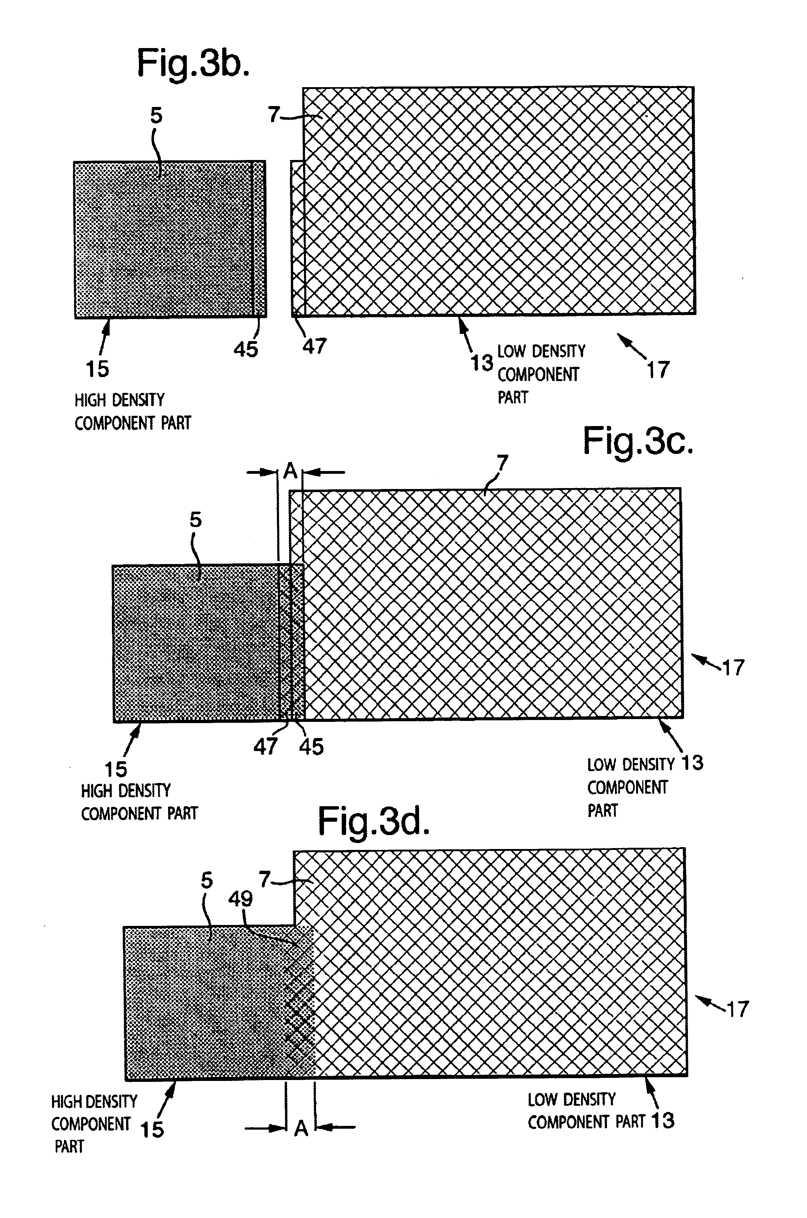
FIG. 3a shows an article 17 manufactured in accordance with the present invention. It is desired that the article 17 comprises two component parts, namely a high density region 15 having a solid internal structure 5 and a low density quickcast region 13 having a honeycomb-like internal structure 7.

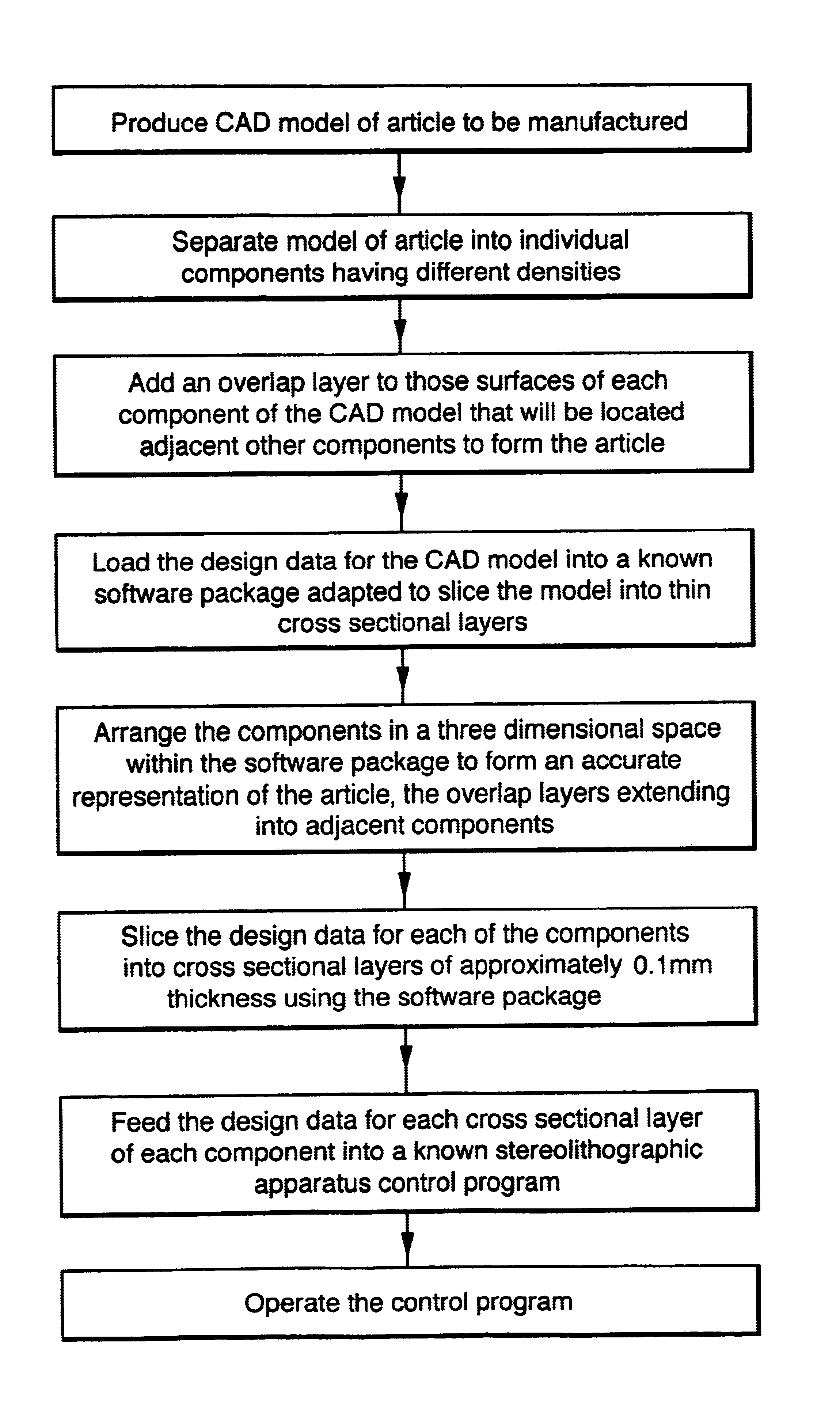
To manufacture the article 17, the design data for the article 17 is first generated using a standard CAD package, and the resulting CAD model of the article 17 is then divided by the operator...


PUM

PropertyMeasurementUnit
depthaaaaaaaaaa
thicknessaaaaaaaaaa
depthaaaaaaaaaa

Abstract

A method of producing an article formed from a photosensitive polymer resin, the article having at least two different densities and the article being a unitary article having substantially no structural joint between regions of different density.

Description

1. Field of the InventionThis invention relates to the field of stereolithography.2. Discussion of Prior ArtStereolithography is a process by which highly accurate solidified articles can be formed from liquid photosensitive polymer resin. When exposed to ultra violet radiation, the photosensitive resin cures to form a solid plastics material.In a known stereolithographic process, a fine, intense ultra violet laser beam is directed on to the liquid surface of the resin. Where the beam makes contact with the resin, the resin cures to a depth of typically 0.15 mm. To allow an article to be formed by curing the resin, it is necessary to split the article into very thin sections, each of approximately 0.1 mm thickness. A movable perforated tray is placed in the resin, initially at a depth of approx 0.1 mm below the surface of the resin. The laser beam is then moved across the surface of the resin to form a solidified trail, representing a cross section of the article, leaving adjacent a...

Claims


Application Information

Patent Timeline
Patent Type & Authority Patents(United States)
IPC IPC(8): B29C67/00
CPCB29C67/0066B29K2995/0064B29C64/135B33Y50/00B33Y50/02
Inventor BAMFORD, MARK D
Owner BAE SYSTEMS PLC
Learn More