

Wavelength measurement apparatus
a technology of measurement apparatus and wavelength, applied in the direction of optical radiation measurement, instruments, spectrometry/spectrophotometry/monochromators, etc., can solve the problem of inability to accurately measure the wavelength in the case of continuous variation of the wavelength of light under measuremen
- Summary
- Abstract
- Description
- Claims
- Application Information
AI Technical Summary
Benefits of technology
Problems solved by technology
Method used
Image

Examples
first embodiment
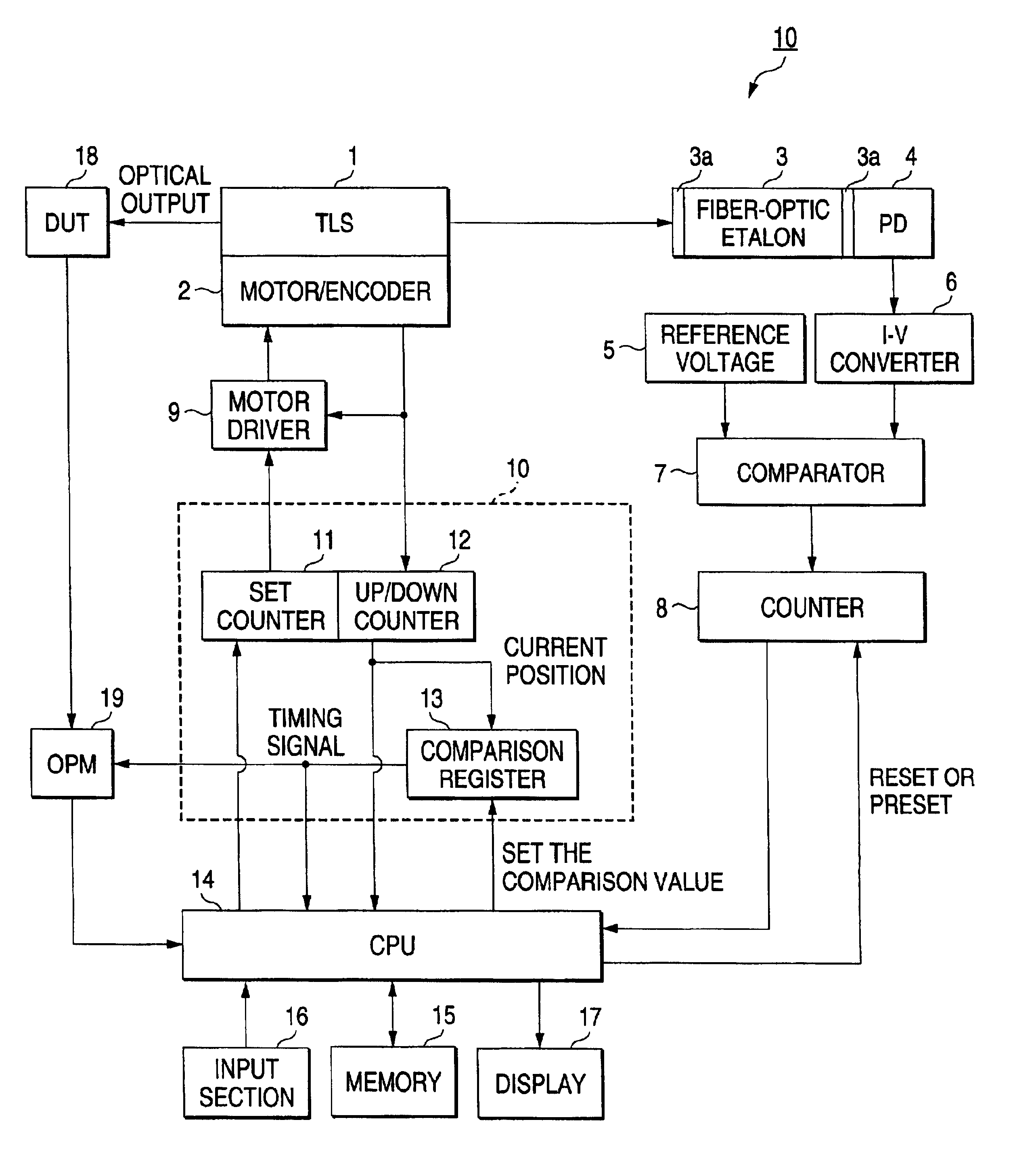
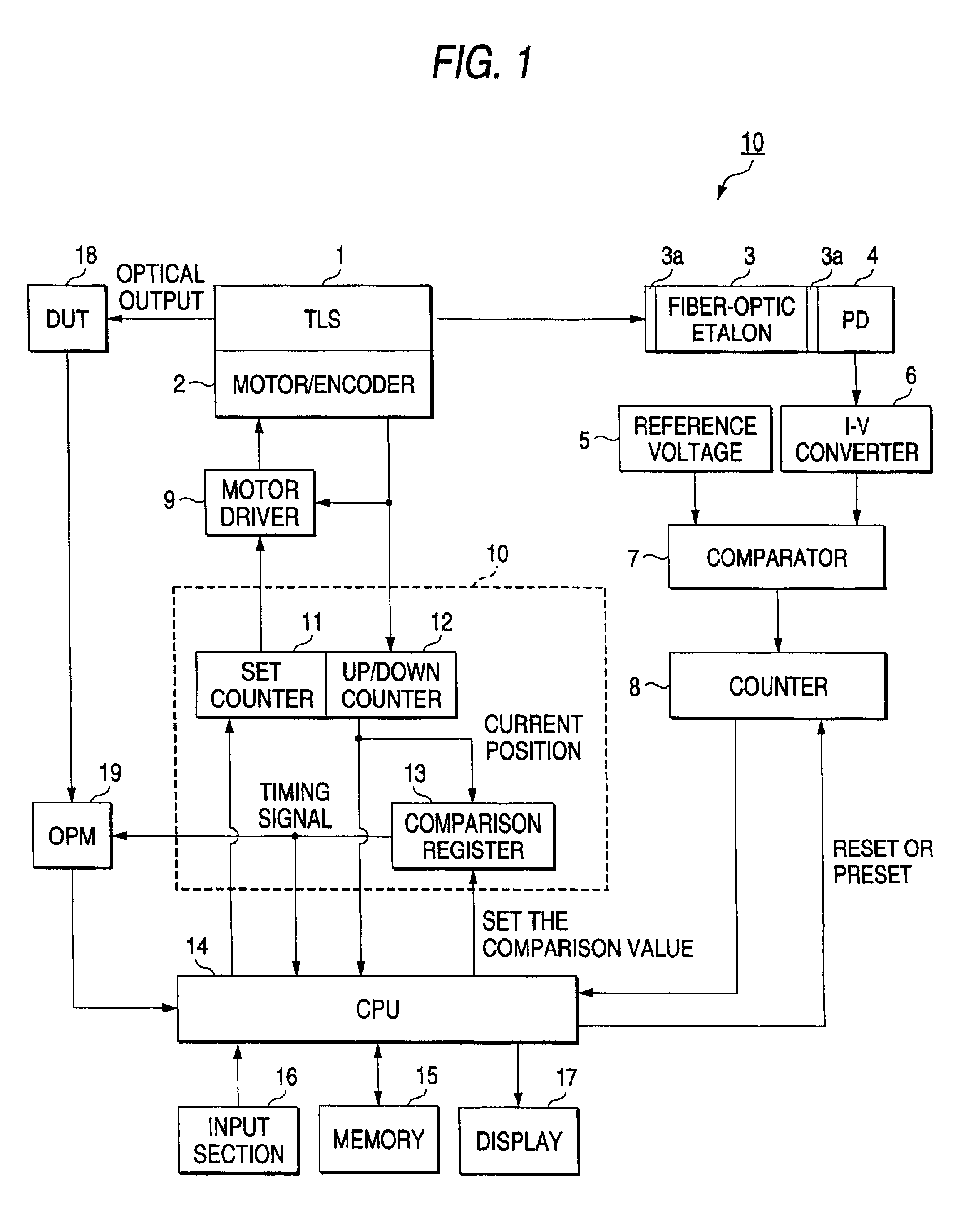
FIG. 1 is a block diagram showing wavelength measurement apparatus according to the first embodiment. The wavelength measurement apparatus 10 comprises a tunable light source (TLS) 1, a motor / encoder 2, fiber-optic Etalon 3, a photodiode (PD) 4, a reference voltage source 5, a current-to-voltage converter (I-V converter) 6, a comparator (COMPARATOR) 7, a counter (COUNTER) 8, a motor driver 9, a motor controller 10, a set counter (SETCOUNTER) 11, an up / down counter (UP / DOWN COUNTER) 12, a comparison register 13, a CPU 14, a memory 15, an input section 16, a display (DISPLAY) 17, and an OPM 19. A DUT (Device Under Test) 18 is shown as a target of measurement.
The tunable light source has a semiconductor laser (LD: Laser Diode) with a non-reflective film supplied on one end, and a tunable structure composed of a diffraction grating and mirrors for adjusting the oscillation of the semiconductor laser. The tunable light source 1 is calibrated in advance so that the oscillation wavelength ...
second embodiment
FIG. 4 is a block diagram showing the configuration of wavelength measurement apparatus 20 according to the second embodiment of the invention. In FIG. 4, same components as those of the aforementioned wavelength measurement apparatus 10 are given the same signs and corresponding description is omitted. The wavelength measurement apparatus 20 is characterized of comprising a photocoupler 21, a photodiode 22, and a reference voltage source 23.
The photocoupler 21 branches the outgoing light of the tunable light source 1 to light under measurement to be incident on the fiber-optic Etalon 3 and reference light to be incident on the photodiode 22 before the fiber-optic Etalon 3. The photodiode 22 outputs a current corresponding to the reference light branched by the photocoupler 21. The reference voltage source 23 applies the reference voltage (counter threshold voltage) corresponding to the current value output from the photodiode 22 to the subsequent comparator 7.
According to the wavel...
third embodiment
FIG. 5 is a block diagram showing the configuration of wavelength measurement apparatus 30 according to the third embodiment of the invention. In FIG. 5, same components as those of the aforementioned wavelength measurement apparatus 20 are given the same signs and corresponding description is omitted. The wavelength measurement apparatus 30 is configured generally the same as the wavelength measurement apparatus 20 according to the second embodiment but is characterized of determining the timing to issue a synchronization signal based on the value of the counter 8.
The memory 15 stores the third table that specifies the variation in the wavelength of light under measurement per unit count value of the up / down counter 12.
Operation of the wavelength measurement apparatus 30 will be described below. The operator sets the sweep start wavelength (WLS) (for example 1499.990 [nm]) in advance at the input section 16. Then the sweep start wavelength (WLS) is stored into the memory 15 by the ...
PUM
 Abstract
Description
Claims
Application Information