Process for transmission laser welding of plastic parts

a technology of transmission laser and plastic parts, which is applied in the direction of layered products, chemistry apparatus and processes, and other domestic articles, can solve the problems of plastic parts adapting and the pressure forces at the contact zone will generally increase, so as to reduce the penetration depth, reduce the loss of reflection, and increase the radiation dispersion

Inactive Publication Date: 2004-10-12
DELPHI TECH INC
View PDF11 Cites 31 Cited by
  • Summary
  • Abstract
  • Description
  • Claims
  • Application Information

AI Technical Summary

Benefits of technology

A great advantage of the process of the invention is that at the contact zone pressure forces due to the interference fit exist, which cause an outer surface portion of the second plastic part and an inner surface portion of the first plastic part to be pressed against each other. Hence, an action of pressure exists directly in this inner contact zone where the welding is to be effected and there is no need for external clamping means for pressing the two plastic parts against each other during the welding process. Moreover, these pressure forces at the contact zone will generally increase during the welding, due to thermal expansion of the plastic materials. As a result, an intimate contact is ensured at the contact zone, during the whole welding process, thereby avoiding the formation of voids in the weld. It follows that high quality welds can be obtained, whereby the welds may also provide an airtight and watertight sealing. Besides, the present process allows to assemble and adjust the plastic parts in their final positions with precision, before the laser welding step. Indeed, the interference fit keeps the two plastic parts in place, without specific hold means. This obviously simplifies the welding process. Furthermore, in case the surfaces in the contact zone are not exactly complementary, as well as in case of burrs on these surfaces, the interference fit will tend to cause the plastic parts to adapt to the shapes of each other. This effect as well as plastic expansion at the weld allow to obtain a uniform weld.
The present method thus provides a process which allows to obtain good quality welds without clamping means. Further benefits of the present process are: (1) precise and contactless heat transmission with improved control of temperature in the heated zones; (2) high and economically interesting welding speeds; (3) possibility of welding parts with different stiffnesses and viscosities.
Another way of creating an interference fit is to provide an annular rib either on the outer surface of the insert element or on the inner surface of the tubular shell, the rib having a thickness such that it interferes with the other part. In such a case, the tubular shell preferably has a circular inner cross-section and the insert element has a cylindrical outer shape with a diameter inferior to the inner diameter of the tubular shell. The use of an annular rib either on the insert element or on the outer shell will provide a continuous annular contact zone between the two pieces.
Additives such as glass fibers and glass globes and other filling materials, increase the dispersion of the radiation and thereby decrease the penetration depth, but they do not completely hinder the penetration through the material, whereby such materials may be also be used for the transmitting part, i.e. the tubular shell, and not only for the absorbing insert element.
The laser beam may have a wavelength ranging from 0.50 to 10.90 .mu.m, preferably between 800 and 1100 nm. Any laser source capable of heating thermoplastic materials may be employed, in particular lasers emitting in the infrared range. Lasers sources emitting in the short-wavelength infrared, such as e.g. a solid-state Nd:YAG laser (.lambda..apprxeq.1064 nm) or a laser diode (.lambda..apprxeq.800 to 1000 nm), are preferred for the welding of thermoplastic parts, but the CO.sub.2 laser is also adapted for many applications. To minimise loss by reflection on the outer surface of the first plastic part, the incident laser beam should preferably be perpendicular to its outer surface.
The interference fit between the two housing part produces radial pressure forces at the contact zone, which ensure an intimate contact between the two parts during the welding. No clamping means are required, and the two housing parts can be precisely assembled before the welding. The present process thus allows to rapidly and efficiently seal plastic housings by means of a laser. It is particularly well suited for welding plastic housing of sensors or actuators, e.g. a camshaft sensor or a fuel tank purge solenoid. It is to be noted that since the present method uses a laser beam, there are no problems of compatibility as with ultrasonic welding, and there is no need for air gaps as with friction welding. Moreover, when a continuous weld is effected, such as e.g. an annular weld all along the contact zone, a sealed connection is obtained, and there is no need for a further sealing means such as e.g. an O-ring.

Problems solved by technology

Moreover, these pressure forces at the contact zone will generally increase during the welding, due to thermal expansion of the plastic materials.
Furthermore, in case the surfaces in the contact zone are not exactly complementary, as well as in case of burrs on these surfaces, the interference fit will tend to cause the plastic parts to adapt to the shapes of each other.

Method used


Image

  • Process for transmission laser welding of plastic parts
  • Process for transmission laser welding of plastic parts

Examples


Embodiment Construction

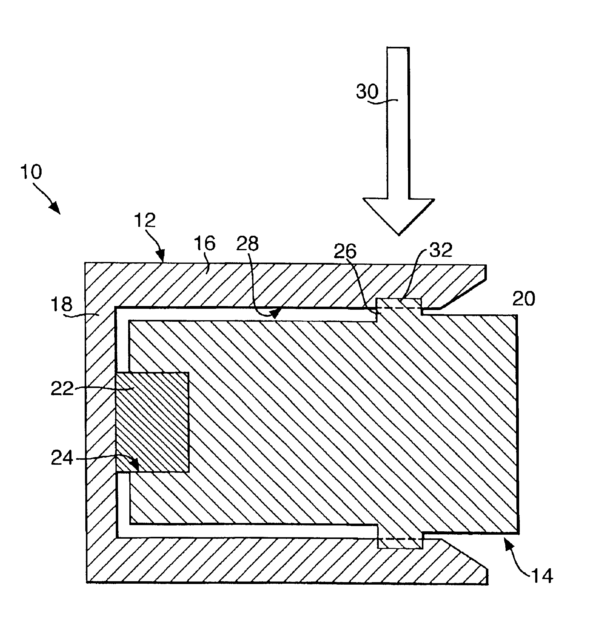
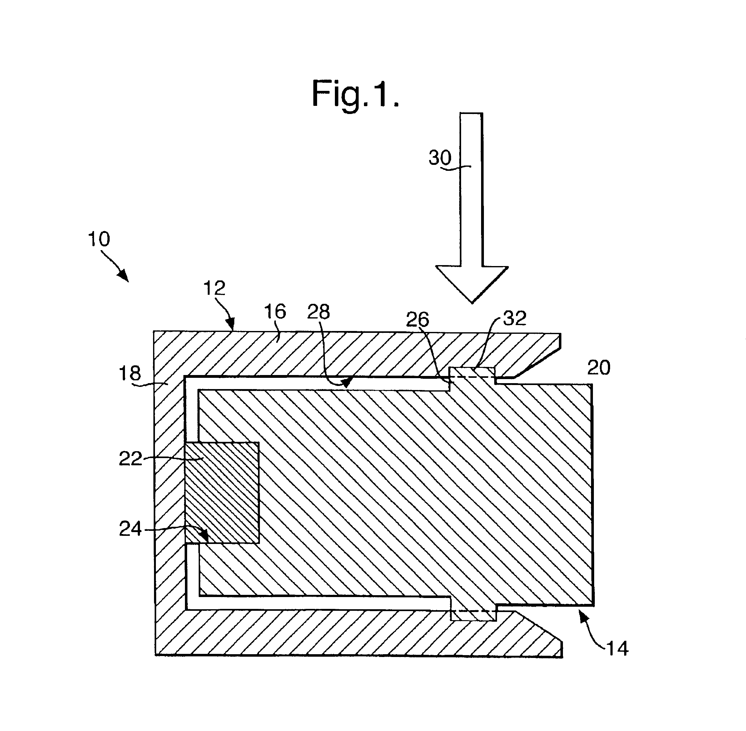
FIG. 1 shows a sectional view of a camshaft sensor 10 with a plastic housing, which is composed of an outer housing part 12 and an inner housing part 14 made of a thermoplastic polymer, preferably including glass fibers. The outer housing part comprises a cylindrical shell 16 closed at one end by a flat bottom 18. The inner housing part 14 comprises a cylindrical element 20 which is partially received in the cylindrical shell 16 of the outer housing part 12. The outer diameter of the cylindrical element 20 is smaller than the inner diameter of the cylindrical shell 16. Reference sign 22 indicates a magnetic sensor, which is arranged in a recess 24 in the internal end of the cylindrical element 20. The magnetic sensor 22 is in abutment against the inner side of the flat bottom 18 of the outer part 12. Although not shown, electrical components are accommodated in the cylindrical element 20 of the inner housing part 14. Such a camshaft sensor 10 allows to detect the variation of magnet...


PUM

PropertyMeasurementUnit
wavelengthaaaaaaaaaa

Abstract

A process for transmission laser welding of a first plastic part and a second plastic part that can be at least partially received in the first plastic part is proposed. The second plastic part is introduced into the first plastic part, to which it is connected by means of an interference fit connection, whereby at least one contact zone between the second plastic part and the first plastic part is formed as a result of this interference fit. A laser beam is directed to impinge on the second plastic part, through the first plastic part, along the at least one contact zone to form a weld.

Description

The present invention generally relates to a process for transmission laser welding of plastic parts.Electrical devices often comprise a plastic housing, in which the electrical components are accommodated. Such housings are generally made of a plurality of plastic parts, which are put together during the assembly of the electrical device, and often a solid connection between the housing parts is desired.In order to solidly connect these housing parts together, various techniques may be employed. For example, ultrasonic welding is a technique which allows to hermetically seal plastic housings. However, it is disadvantageous since solder connections on the electrical components and also the components themselves may be destroyed on account of the ultrasonic vibrations, ultimately making the electrical device unusable.When the housing parts have a rotational symmetry, it is possible to use a friction welding process. This technique is however constraining, as the arrangement of the el...

Claims


Application Information

Patent Timeline
Patent Type & Authority Patents(United States)
IPC IPC(8): B29C65/14B29C65/00B29C65/16B29C65/72B29C65/78B29C35/08
CPCB29C65/1635B29C65/66B29C65/72B29C65/7802B29C65/7855B29C66/534B29C66/65B29C66/8264B29C66/612B29C66/8262B29C65/1654B29C65/1609B29C65/1677B29C65/1616B29C65/1619B29C65/1674B29C65/565B29C66/342B29C66/73121B29C2035/0822B29K2023/00B29K2033/12B29K2067/00B29K2067/003B29K2067/006B29K2077/00B29K2309/08B29K2995/0065B29K2995/0067B29K2995/0068B29K2995/0069B29L2031/3061B29C65/1612B29C66/73921B29C66/71B29C66/7315B29L2031/3481B29C66/73122B29C66/1122B29L2031/7172B29K2059/00
Inventor RUOTSALAINEN, SAMI
Owner DELPHI TECH INC
Why Eureka
Try Eureka