Multi-coil eddy current proximity probe system

a proximity probe and coil technology, applied in the direction of magnetic property measurement, material magnetic variables, instruments, etc., can solve the problems of temperature stability problems within the system, component and manufacturing variations also generally burden the system, and the above-delineated system is burdened by temperature errors, so as to eliminate temperature errors

Inactive Publication Date: 2004-10-12
BENTLY NEVADA INC
View PDF43 Cites 56 Cited by
  • Summary
  • Abstract
  • Description
  • Claims
  • Application Information

AI Technical Summary

Benefits of technology

Another further object of the instant invention is to provide the multi-coil eddy current proximity probe system as characterized above which eliminates temperature errors, and manufacturing and component variations as a consequence of the instant invention including them in a closed loop feedback and control system which extends all the way out to a tip of the probe.

Problems solved by technology

The above-delineated system is burdened by temperature errors due to temperature variations in the multi-conductor cables, the coil and the electronics associated with the signal conditioning circuitry.
Additionally, temperature variations in the targets themselves cause temperature stability problems within the system.
Furthermore, component and manufacturing variations also generally burden the system.
Moreover, and more particularly, sense coil resistance of the probe is one principle source of temperature drift error.
Thus, the process of measuring gap as a function of the impedance of the coil is susceptible to this error thereby resulting in inaccurate proximity probe measurements as a consequence of the drift error causing a false appearance of a gap change between the target and probe.
Such inconsistencies in temperature stability of the proximity probe result in unpredictable and unreliable measurements even when the proximity probe is functioning in its linear range of operation.
Thus, U.S. Pat. No. 5,854,553 to Barclay, et al. also suffers from, inter alia, the same temperature instability problems delineated hereinabove.
Moreover, known multiple coil proximity switch devices, distance measurement devices, and metal detecting circuits are also plagued by, inter alia, temperature drift error and component and manufacturing variations.

Method used


Image

  • Multi-coil eddy current proximity probe system
  • Multi-coil eddy current proximity probe system
  • Multi-coil eddy current proximity probe system

Examples


Embodiment Construction

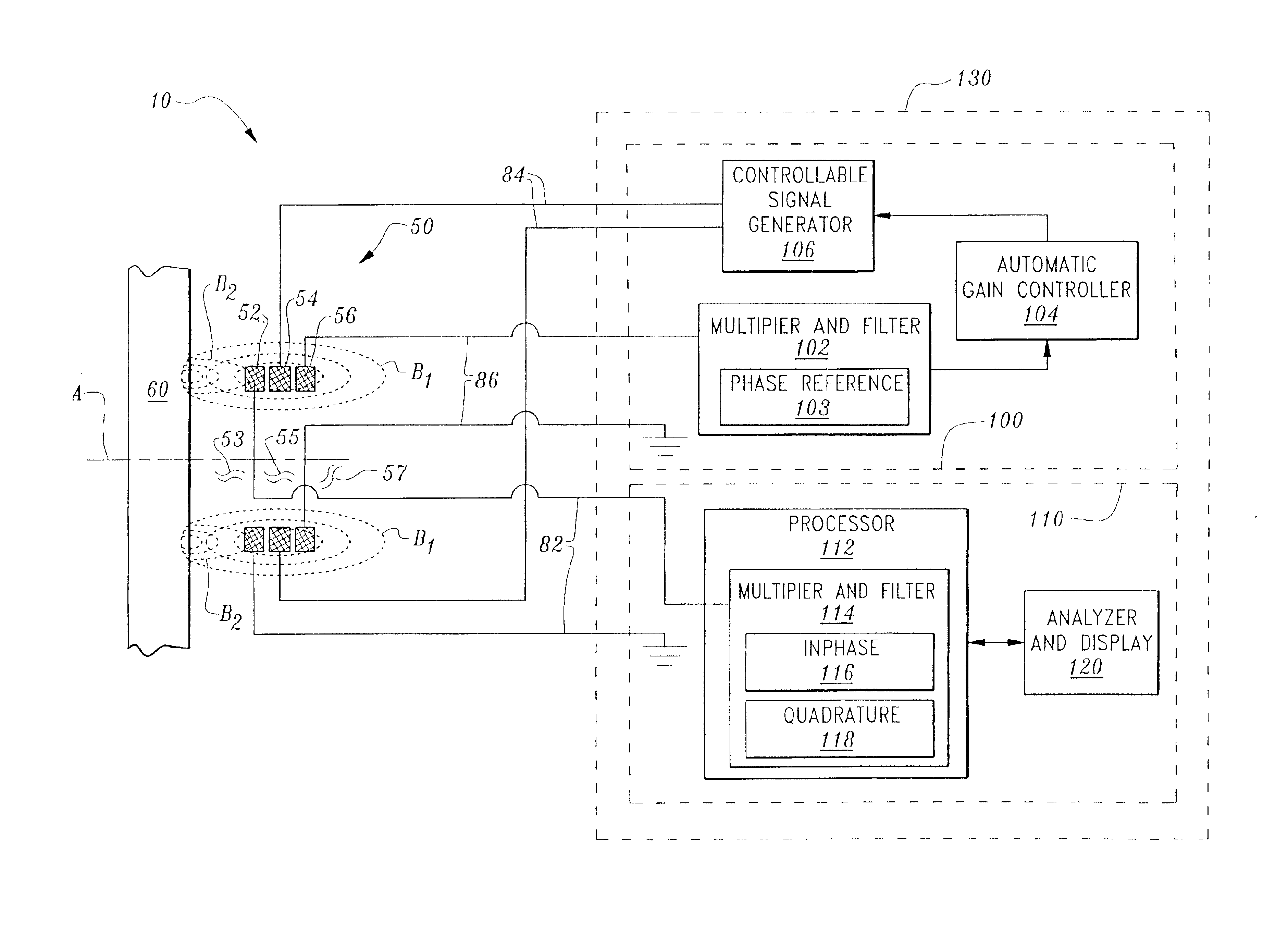
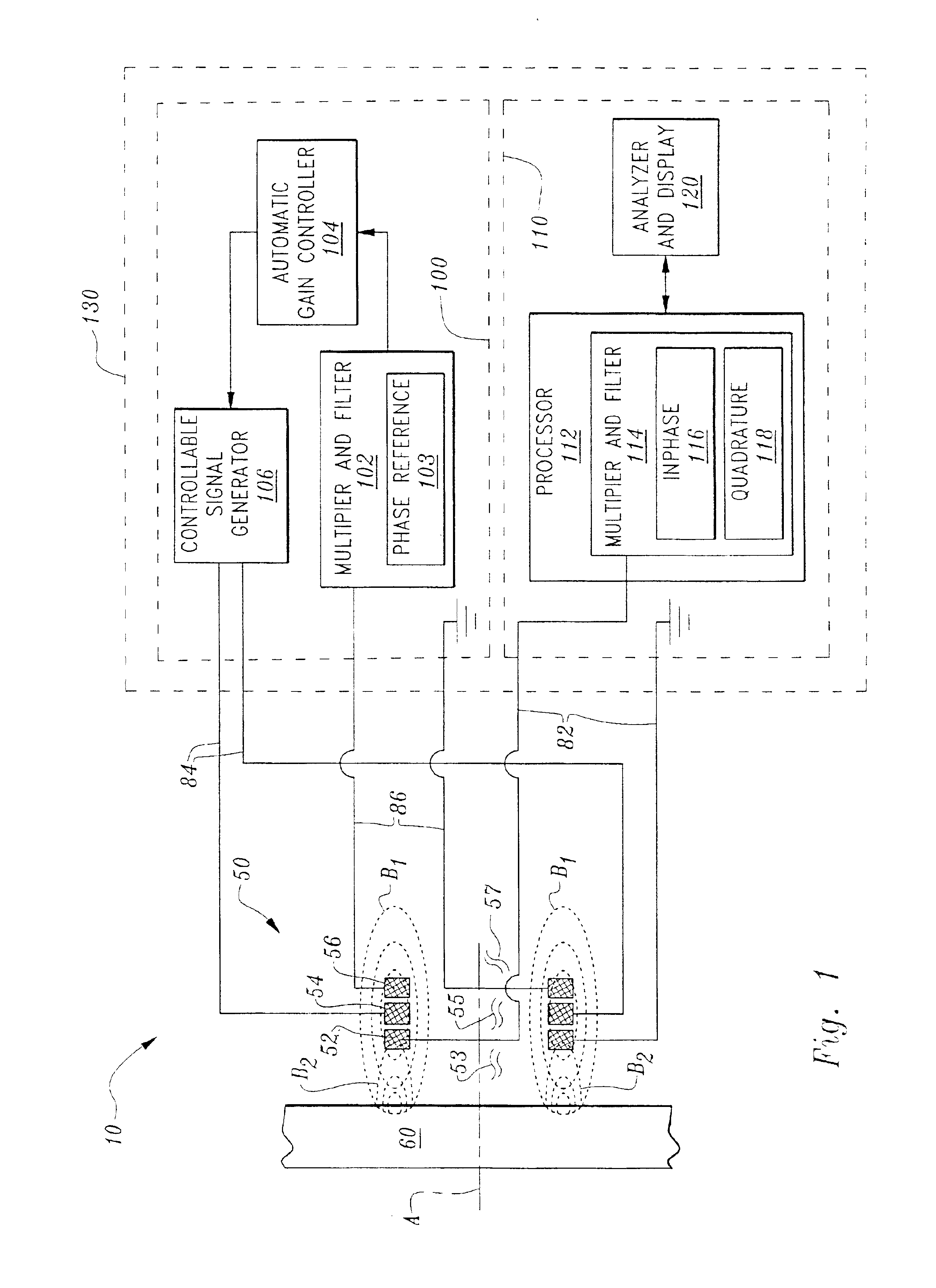
Considering the drawings, wherein like reference numerals denote like parts throughout the various drawing figures, reference numeral 10 is directed to the multi-coil eddy current proximity probe system according to the present invention.

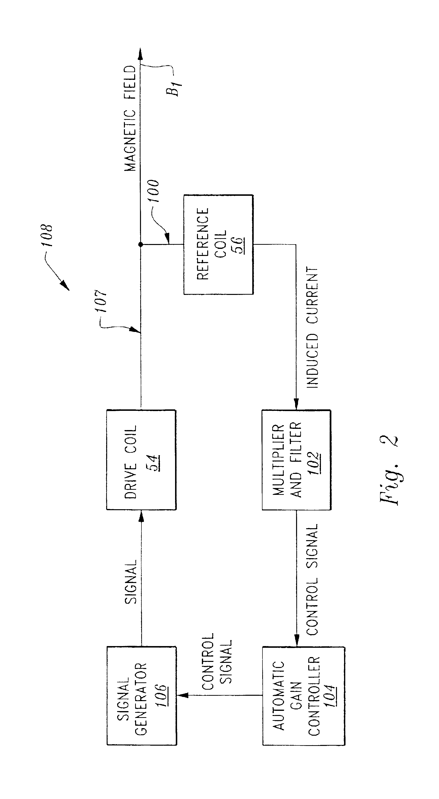
In its essence, and referring to FIG. 1, the multi-coil eddy current proximity probe system 10 includes a multi-coil array 50 comprised of a drive coil 54 engendering eddy currents in an adjacent conductive target object 60, a sense coil 52 interposed between the drive coil 54 and the target object 60 for sensing current induced in the sense coil 52 by the eddy currents engendered in the target object 60, and a reference coil 56 situated behind the drive coil 54 and carrying a drive coil induced alternating current or reference current. Additionally, the system 10 includes a signal conditioning and control system 130 comprising a feedback and control loop 100 operatively coupling the reference coil 56 to the drive coil 54 for controlling the alterna...


PUM


Abstract

A proximity probe system comprising a multi-coil proximity probe including a drive coil, a sense coil and a reference coil. The system includes a signal generator driving the drive coil with an alternating current for creating a magnetic field that induces eddy currents in a proximate conductive object resulting in an eddy current induced magnetic field emanating therefrom. The sense coil is interposed between the object and the drive coil for outputting an object induced alternating current that is detected by the system and correlated to a position of the object relative to the probe. The reference coil is positioned to be inductively coupled to the drive coil for carrying a drive coil induced alternating current that is detected, conditioned and feedback to the signal generator for controlling the magnetic field radiating from the drive coil while sensing the the object induced alternating current in the sense coil.

Description

The instant invention relates generally to eddy current proximity probe systems for determining displacement motion and position of an observed conductive target object and in particular, to a multi-coil eddy current proximity probe system utilized for monitoring, for example, rotating and reciprocating machinery.Proximity probe systems that analyze and monitor, for example, rotating and reciprocating machinery are known in the art. These systems typically include one or more proximity probes: noncontacting eddy current displacement devices operating on the eddy current principle for measuring displacement motion and position of an observed conductive target object relative to one or more of the displacement devices. Typically, each proximity probe is located proximate a target object such as a rotating shaft of a machine or an outer race of a rolling element bearing being monitored and is connected to signal conditioning circuitry which in turn is coupled to analyzing apparatus for...

Claims


Application Information

Patent Timeline
Patent Type & Authority Patents(United States)
IPC IPC(8): G01B7/00G01B7/14G01D5/12G01D5/20
CPCG01B7/001G01D5/2053G01B7/14
Inventor SLATES, RICHARD DALE
Owner BENTLY NEVADA INC
Why Eureka
Try Eureka