Controlling the range and resolution of offset correction applied to the output of a charge coupled device

a technology of offset correction and output, which is applied in the direction of color television details, color signal processing circuits, television systems, etc., can solve the problems of providing implementation challenges and normally consuming more power, and achieve the effect of minimizing the introduction of additional undesirable components, and reducing the introduction of nois

Inactive Publication Date: 2004-10-19
TEXAS INSTR INC
View PDF8 Cites 17 Cited by
  • Summary
  • Abstract
  • Description
  • Claims
  • Application Information

AI Technical Summary

Benefits of technology

An aspect of the present invention provides a designer the ability to control the correction range and to attain low correction resolution while minimizing the introduction of additional undesirable components (noise) in the CCD output voltages. The introduction of noise can generally be minimized by minimizing the number of stages in the correction circuit. Minimizing the number of stages has the additional benefit of reducing power consumption requirements.
According to another aspect of the present invention, the ratio of Cfdac to Cfpga is maintained to be a constant, which allows the correction resolution to potentially equal a least significant bit of an ADC (used to sample the output of the PGA). That is, the present invention allows offset correction to be effected by minute (small) amounts limited only by the resolution of a later sampling ADC.
Thus, once total desired amplification of the input signal (Vi) is determined, partial amplifications for each of the two stages may be assigned. The capacitances (Csinp, Cspga, Cfpga and Cfcds) may be configured consistent with the assigned partial amplifications. The capacitances Ccdac and Cfdac may be configured consistent with the objectives noted above with reference to correction range and correction resolution. By using the features of the present invention, offset correction, which quickly removes (at least substantially) the undesirable components, may be implemented.

Problems solved by technology

While a solution could be implemented using only a single DAC, the same would typically require a DAC of very high resolution, which provides challenges in implementation and would normally consume more power.

Method used


Image

  • Controlling the range and resolution of offset correction applied to the output of a charge coupled device
  • Controlling the range and resolution of offset correction applied to the output of a charge coupled device
  • Controlling the range and resolution of offset correction applied to the output of a charge coupled device

Examples


Embodiment Construction

1. Overview and Discussion of the Invention

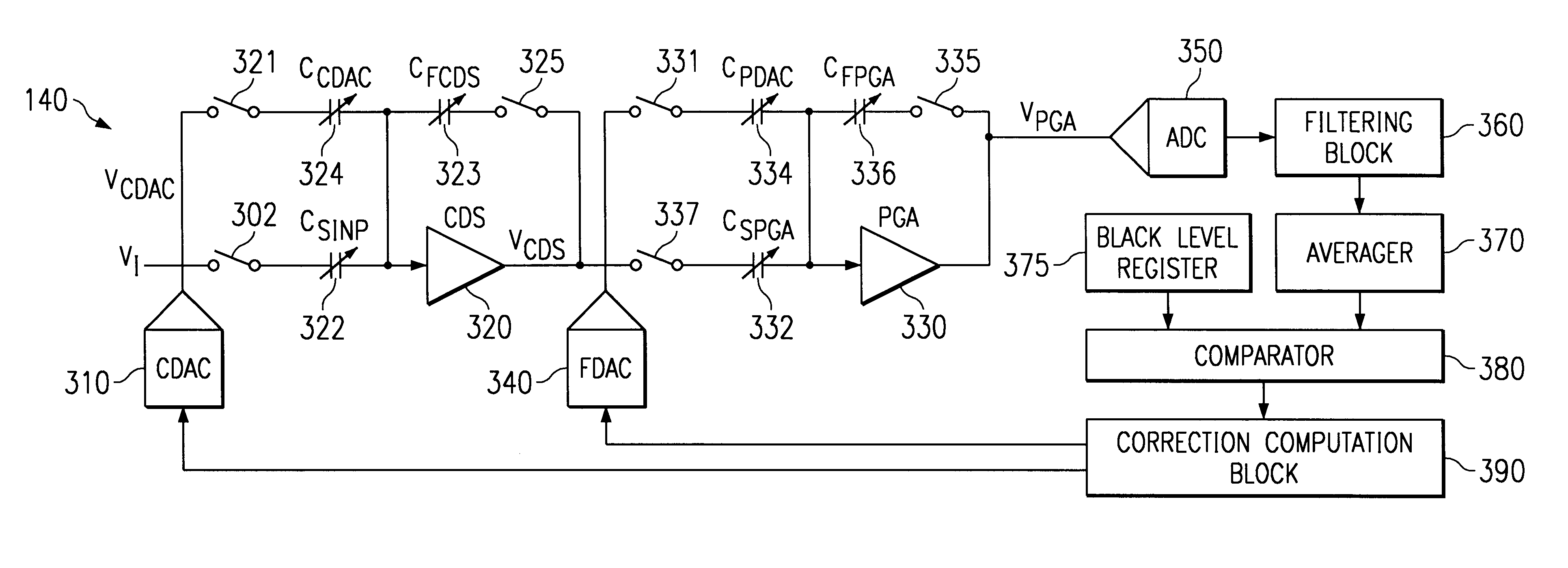
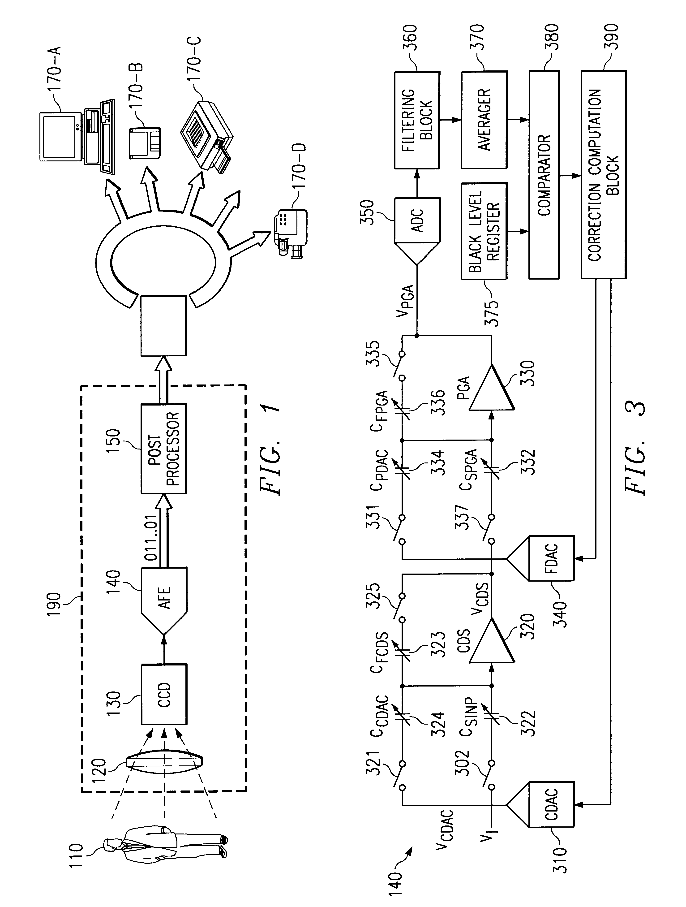
An aspect of the present invention enables the correction range and resolution to be controlled by appropriate configuration of capacitors used in conjunction with amplifiers in the offset correction circuits. The correction range is maintained to be a constant irrespective of the gain sought to be achieved on the input signal, and the correction resolution can be as low as that possible by a least significant bit of an analog to digital converter (ADC) used to sample the corrected signal (in the process of digitizing the signal representing light).

Several aspects of the invention are described below with reference to example environments for illustration. It should be understood that numerous specific details, relationships, and methods are set forth to provide a full understanding of the invention. One skilled in the relevant art, however, will readily recognize that the invention can be practiced without one or more of the specific detai...


PUM


Abstract

An offset correction circuit which enables a designer to control the correction range irrespective of the amplification sought to be achieved to the image component of the input signal. The offset correction further enables the designer to perform offset correction to a low resolution. Both range and resolution can potentially be attained using only two stages thereby minimizing power consumption and also minimizing introduction of any undesirable components.

Description

BACKGROUND OF THE INVENTION1. Field of the InventionThe present invention relates to charge coupled devices (CCD) typically used to capture color pictures in digital form, and more specifically to a method and apparatus for controlling the range and resolution of the offset applied to the output of the CCDs.2. Related ArtCharge coupled devices (CCDs) are often used to capture images received in the form of light. A CCD typically contains several pixels, with each pixel holding an amount of charge proportionate to the intensity of incident light and the length of time the light is allowed to fall on the pixel. The charge can be later translated to a voltage level and / or digital data for further processing and / or storing (in mass non-volatile storage). CCDs thus find application in devices such as digital cameras and scanners as is well known in the relevant arts.A correction (termed "offset correction") is often applied to the output (i.e., voltage or digital data in the above paragr...

Claims


Application Information

Patent Timeline
Patent Type & Authority Patents(United States)
IPC IPC(8): H04N5/217H04N5/357H04N5/372H04N5/378
CPCH04N5/367H04N25/68
Inventor MUKHERJEE, SUBHASHISHKULHALLI, SUHAS R.
Owner TEXAS INSTR INC
Why Eureka
Try Eureka