Logic circuit design equipment and method for designing logic circuit for reducing leakage current

a logic circuit and design equipment technology, applied in the field of logic circuit design equipment and logic circuit design equipment, can solve the problems of not always being able to produce logic circuits displaying minimal leakage current, increasing the leakage current that has accompanied microfabrication processing, and not always being able to map to constitute logic circuits displaying minimum leakage curren

Inactive Publication Date: 2004-11-02
KK TOSHIBA
View PDF6 Cites 104 Cited by
  • Summary
  • Abstract
  • Description
  • Claims
  • Application Information

AI Technical Summary

Problems solved by technology

Accordingly, it is not always possible to produce a logic circuit displaying minimal leakage current.
The increase in leakage current that has accompanied microfabrication processing has been a problem in recent years.
However, in such a case, the possibility that the difference in the leak currents in cells constituting the logic circuit may depend on the state in which input has not been considered.
Accordingly, there is a problem that mapping to constitute a logic circuit showing minimum leakage current is not always performed.
Furthermore, in the recent appliances such as portable telephones and portable terminals, if leakage current during standby time were reduced it would be possible to greatly lengthen the life of a battery.

Method used


Image

  • Logic circuit design equipment and method for designing logic circuit for reducing leakage current
  • Logic circuit design equipment and method for designing logic circuit for reducing leakage current
  • Logic circuit design equipment and method for designing logic circuit for reducing leakage current

Examples


first embodiment

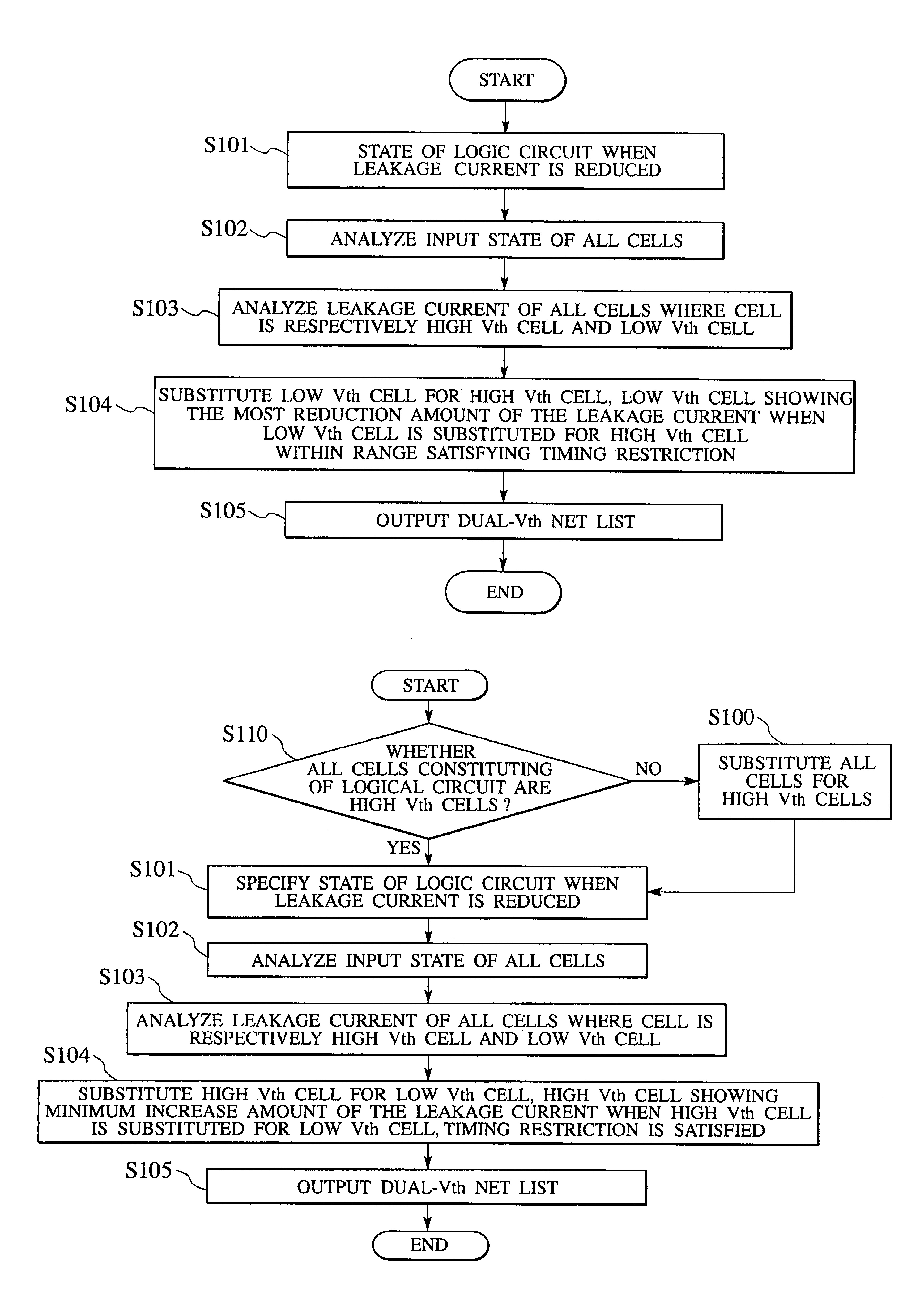
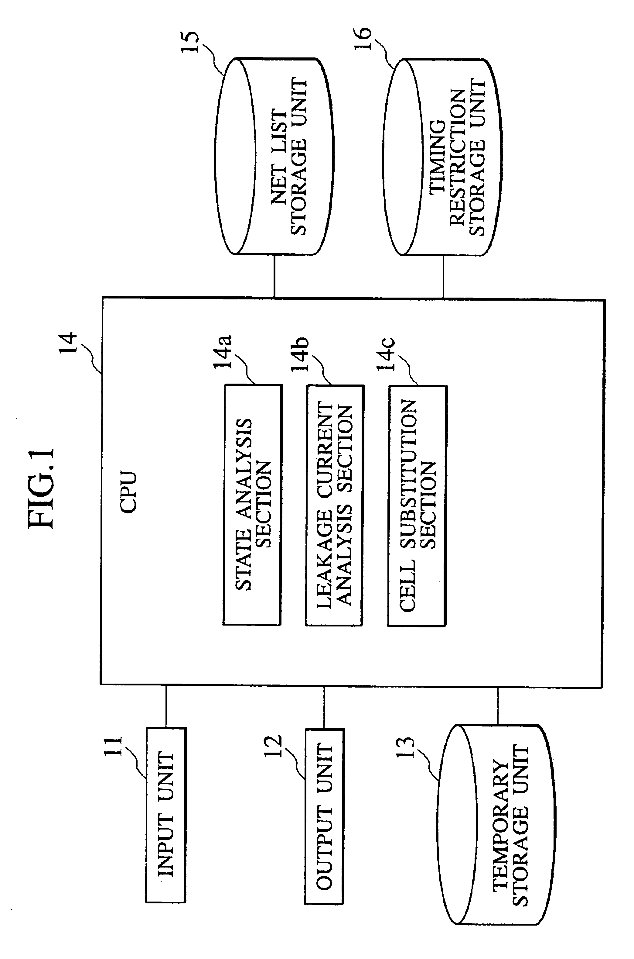
As shown in FIG. 1, a logic circuit design equipment according to the present invention has a processing control unit (CPU) 14, a temporary storage unit (main storage unit) 13, an input unit 11, an output unit 12, a net list storage unit 15 and a timing restriction storage unit 16.

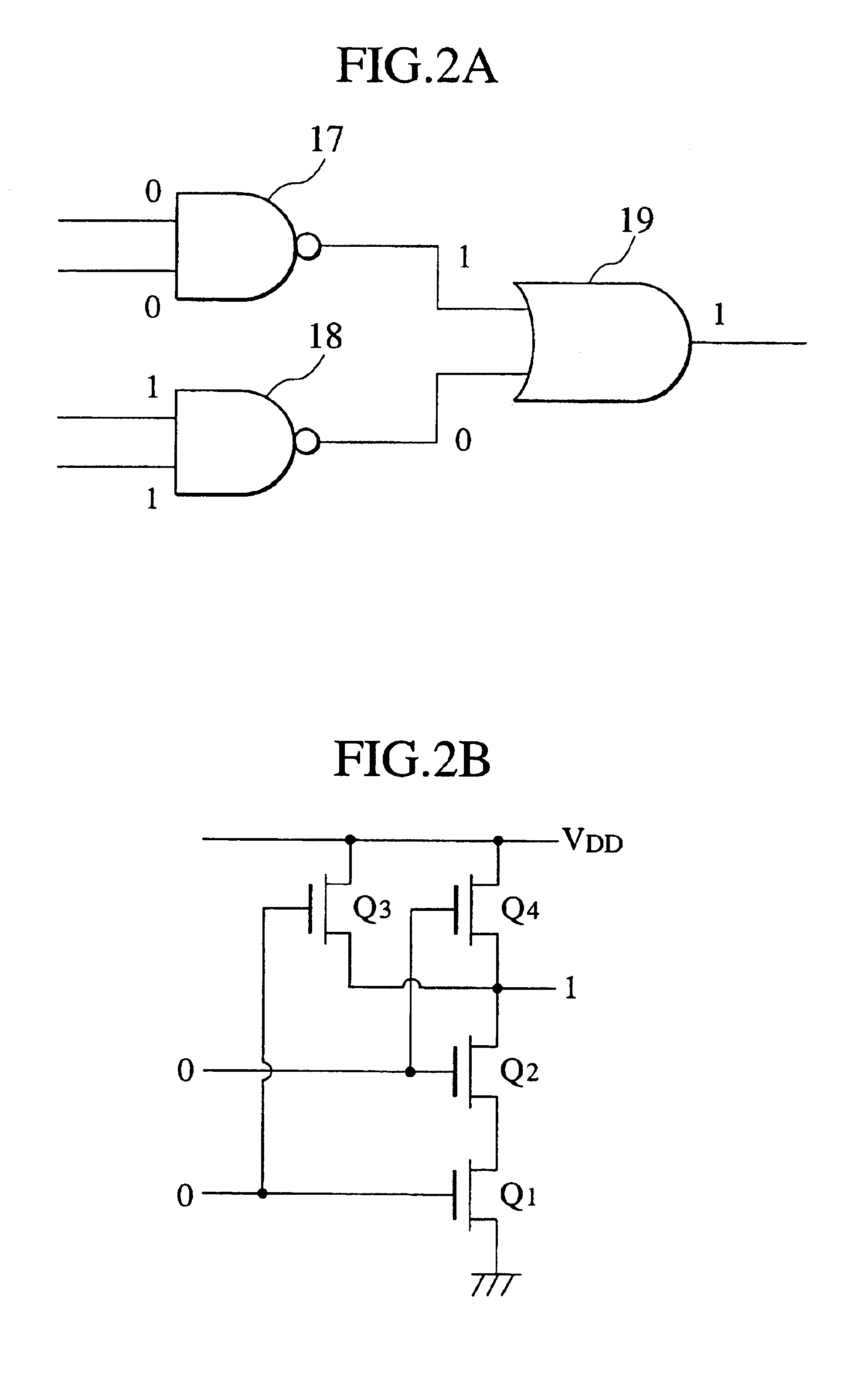
The CPU 14 controls the whole of the logic circuit design equipment according to the first embodiment of the present invention. The CPU 14 is constituted by a state analysis section 14a, a leakage current analysis section 14b and a cell substitution section 14c. In the embodiments of the present invention, a "cell" refers to a base unit constituting a logic circuit such as a logic gate, a flip-flop, and the like, which is called an "instance". For example, a two-input NAND gate 17 and 18, and a two-input OR gate 19 which are logic gates, as shown in FIG. 2, are cells. The two-input NAND gate 17 and 18 are included in CMOS transistors Q1 to Q4 as shown in FIG. 2B, respectively. In the cell, in terms of a th...

second embodiment

(Constitution of Logic Circuit Design Equipment)

The logic circuit design equipment according to the second embodiment of the present invention has a processing control unit (CPU) 24, an input unit 21, an output unit 22, a temporary storage unit 23, a RTL (Resister Transfer Level) storage unit 25, a net list storage unit 26, a library storage unit 27, a state data storage unit 28 and a timing restriction storage unit 29 connected to the CPU 24, as shown in FIG. 6.

The CPU 24 controls the whole of the logic circuit design equipment according to the second embodiment of the present invention, and is constituted by a logic generation section 24a, a technology mapping section 24b, a state analysis section 24c, a leakage current analysis section 24d and a mapping selection section 24e.

The logic generation section 24a has a function of analyzing words and syntaxes to generate syntax data. Moreover, the logic generation section 24a has a wither function of analyzing syntax data and analyzing...

third embodiment

(Constitution of Logic Circuit Design Equipment)

The logic circuit design equipment according to a third embodiment of the present invention of the present invention has a processing control unit (CPU) 34, an input unit 31, an output unit 32, a temporary storage unit (main storage unit) 33, a RTL storage unit 35, a net list storage unit 36, a library storage unit 37, a state data storage unit 38, and a timing restriction storage unit 39 connected to the CPU 34, as shown in FIG. 11.

The CPU 34 has a logic generation section 34a, a technology mapping section 34b, a state analysis section 34c, a leakage current analysis section 34d, a mapping selection section 34e and a cell substitution section 34f.

Since the structures of the state analysis section 34c and the leakage current analysis section 34d are substantially the same as those of the state analysis section 24c and the leakage current analysis section 24d shown in the second embodiment of the present invention, duplicate description...


PUM


Abstract

A logic circuit design equipment and a logic circuit design method include analyzing input states of all of first cells, respectively, analyzing leakage currents of all of first cells in a case where each first cell is high Vth cell showing a small leakage current at a low speed operation and low Vth cell showing a large leakage current at a high speed operation, respectively, and substituting the first cells for second cells within a range satisfying a timing restriction. Herein, a threshold of the second cell is different from a threshold of the first cell.

Description

The applicant is based upon and claims the benefit of priority from prior Japanese Patent Application P2001-103695, filed Apr. 2, 2001; the entire contents of which are incorporated by reference therein.1. Field of the InventionThe present invention relates to a logic circuit design equipment and a method for designing a logic circuit. The present invention relates more particularly to a technology for reducing leakage current.2. Description of the Related ArtAs the voltage used for driving large scale integrated circuits has reduced in recent years, the threshold values (Vth) of transistors have increasingly been lowered. The lowering of the threshold values increases sub-threshold leakage current (hereinafter referred to as a leakage current). This leakage current flows during an active periods when the circuit is in operation, as well as during standby periods when circuit operation has been stopped.As a technique to reduce such leakage current, Dual-Vth technology has been known...

Claims


Application Information

Patent Timeline
Patent Type & Authority Patents(United States)
IPC IPC(8): G06F17/50H01L21/82H01L21/8234H01L27/088H03K19/00
CPCG06F17/505G06F30/327
Inventor USAMI, KIMIYOSHIKAWABE, NAOYUKIKITAHARA, TAKESHIKANAZAWA, MASAHIRO
Owner KK TOSHIBA
Why Eureka
Try Eureka