Rollercoaster launch system

a technology of rollercoaster and launch system, which is applied in the direction of roller drums, amusements, entertainment, etc., can solve the problems of limiting accelerating the carts at the start of the ride, and unable to increase the height of the ramp without considerable costs

Inactive Publication Date: 2005-01-04
VEKOMA RIDES ENG
View PDF3 Cites 18 Cited by
  • Summary
  • Abstract
  • Description
  • Claims
  • Application Information

AI Technical Summary

Benefits of technology

The invention relates to a roller coaster with a launching system that connects temporarily to rollercoaster carts in order to place the carts in motion. The method for launching rollercoaster carts according to the invention comprises pressurizing at least one hydraulic accumulator in a launching system. The launching system includes a gripping conus, a connecting wire and a winch system. The winch drum in the winch system is connected to the hydraulic motor, a turning sheave, and a lifting cylinder that moves the conus to a starting position lifting the wire to the starting position. By connecting the connecting conus and receiving conus together, the hydraulic motor connected to the roller carts is energized moving at least one roller cart up to a predetermined speed using the hydraulic motor.

Problems solved by technology

However the height of this ramp cannot be increased without considerably costs.
Also constructional problems and environmental issues limit the height of this ramp.
However accelerating the carts at the start of the ride has one strong disadvantage.
The needed power of the system to pull the carts to the top of the ramp can be low because the carts do not move at high speeds.
Not only the launching system becomes expensive also the connection to the power grid becomes problematic.

Method used


Image

  • Rollercoaster launch system
  • Rollercoaster launch system
  • Rollercoaster launch system

Examples


second embodiment

FIG. 9 shows the booster system wherein the booster system comprises a cylinder medium separator (104) between accumulator (92) and cylinder (74). The medium separator fluid can be water, water based hydraulic fluid, oil-based hydraulic fluid, environmentally friendly hydraulic fluid, oil, and / or biodegradable hydraulic fluid. A closing valve can be added between the cylinder (74) and the accumulator system (92) to shut-off and separate respective parts. Also, a closing valve can be added between the cylinder medium separator (104) and the cylinder (74). Finally, a multiple connecting valve (120) can be added between the cylinder (74) and the accumulator system (92).

Also in FIG. 9, a cylinder (74) is fully retracted after launching carts (22). For a new launching procedure, cylinder (74) has to be extended to its starting position, with the rod (99) fully extended from the cylinder. In order to launch, the rod (99) is pulled into the cylinder. The force that the winch system can exe...

third embodiment

FIG. 14 shows launching system (8) with booster system (9) attached to it wherein a valve (120) is located between accumulator (92) and cylinder (74), which can connect volume (123) to the accumulator system (94) or the environment.

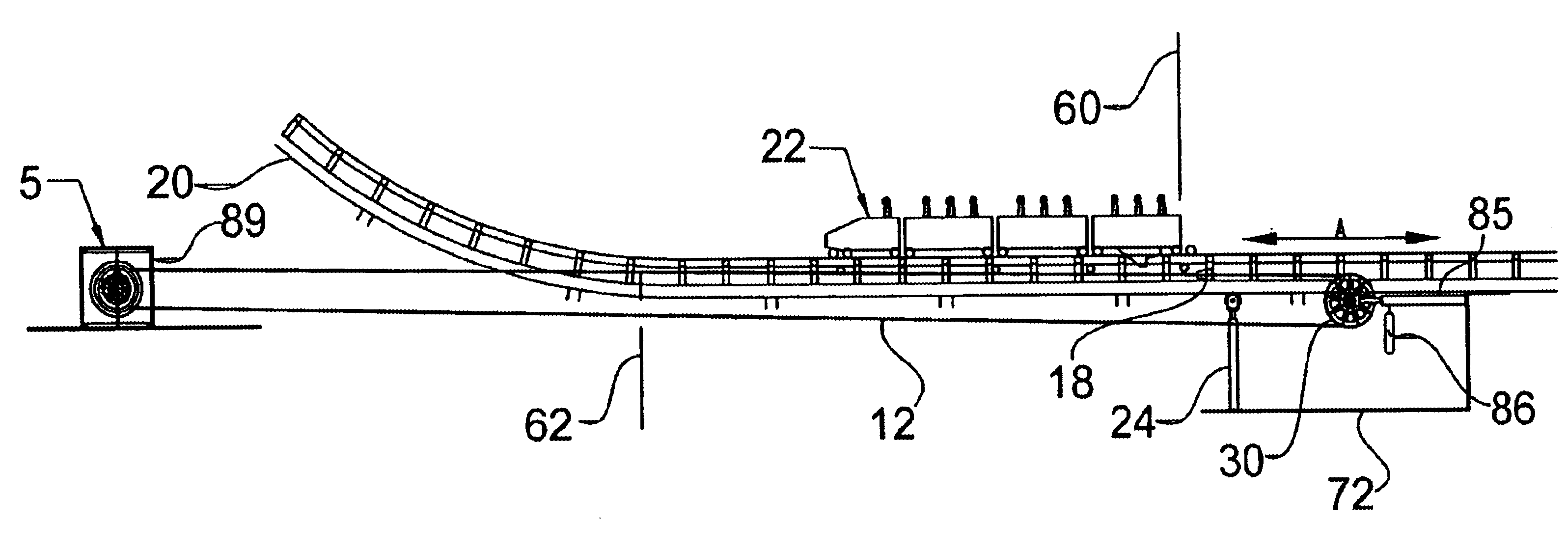
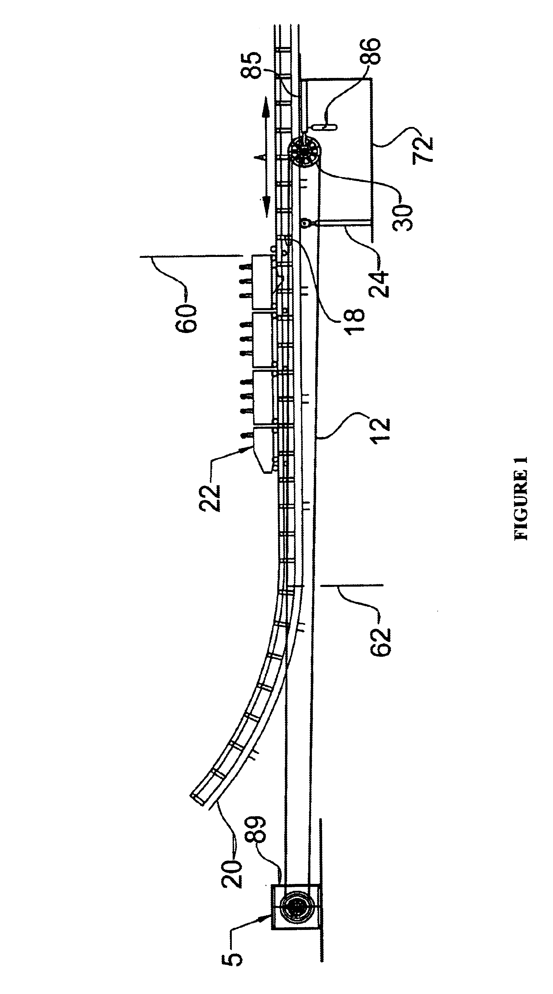
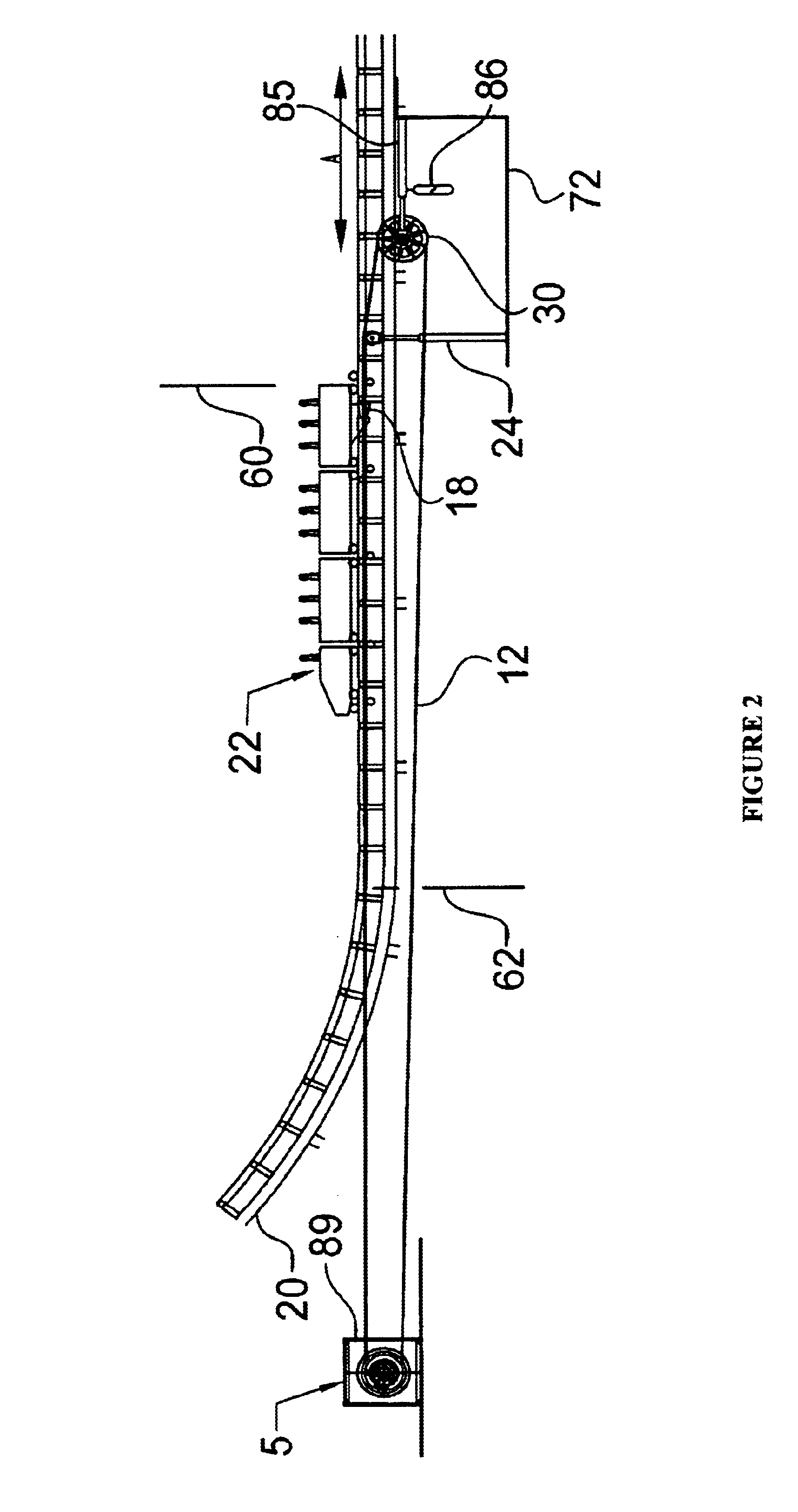
This invention contemplated a method for launching a set of rollercoaster carts comprising:a. pressurizing a plurality of hydraulic accumulators in the a launching system;b. bringing a connecting conus (18) to its starting position;c. lifting a connecting wire at its starting position (60);d. connecting the connecting cone (18) and a receiving cone (95);e. energizing a hydraulic motor and speeding up a plurality of carts;f. lowering the speed of the connection wire;g. disconnecting the connecting conus (18) and the receiving conus (95);h. lowering the connecting wire (12);i. returning connection conus (18) to the starting position; andj. bringing forward another plurality of carts.

This invention also contemplates a method for emergency braking rollercoast...


PUM


Abstract

The invention is a launching system made of a gripping conus connected to a wire that is connected to a winch system, a turning sheave, and a lifting cylinder that is affixed to a base, wherein the winch system has a motor driven hydraulic pump connected to an accumulator system connected to a hydraulic motor that drives a winch drum, and wherein an attached booster system is made of a cylinder connected to accumulator system and a set of sheaves connected to wire that is connected to a gripping conus that moves or stops a cart.

Description

FIELD OF THE INVENTIONThe present invention relates to a rollercoaster launching system and booster system with an increased efficiency as to lower the maximum power of the launching system. The invention also relates to a method for both launching and stopping the rollercoaster carts.BACKGROUND OF THE INVENTIONIn general, rollercoasters are useful amusement park devices comprised of a car supported in a frame that causes the cart to follow a path where the rider experiences high speeds and gravitational forces due to loops, turns and drops. In conventional rollercoasters the carts are pulled to the top of a ramp to provide the carts with the energy needed to complete the ride. During the ride the carts convert the gained potential energy into kinetic energy i.e. speed. Since the potential energy is dependent on the height of the ramp a higher ramp makes a longer track or higher speeds possible. However the height of this ramp cannot be increased without considerably costs. Also con...

Claims


Application Information

Patent Timeline
Patent Type & Authority Patents(United States)
IPC IPC(8): A63G7/00
CPCA63G7/00
Inventor ROODENBURG, JOOPDE VIN, PETER
Owner VEKOMA RIDES ENG
Why Eureka
Try Eureka