Apparatus for treating a gas stream

a gas stream and apparatus technology, applied in the field of apparatus for treating gas streams, can solve the problems of excessively long silencer assemblies and problems, and achieve the effect of easy tensioning and convenient hooking

Inactive Publication Date: 2005-01-04
GAULT ANTHONY JOHN +1
View PDF12 Cites 26 Cited by
  • Summary
  • Abstract
  • Description
  • Claims
  • Application Information

AI Technical Summary

Benefits of technology

A particularly preferred form of tensioning mechanism, which also provides a measure of extensibility in the securement of the straps, comprises a plurality of straps carrying a hook or other securing means at each end thereof which are to engage with a tensioning ring located upon the end cap of the silencer assembly, for example by a continuous or discontinuous raised annular peripheral rim to the end cap or an axial extension of the cylindrical wall of the terminal tubular body member of the silencer assembly. The tensioning ring is formed with a wavy, sinusoidal, crenellated, zigzag or other undulating shape which provides localised axially elevated portions of the ring with which the hooks of the straps are to engage, axially lower portions which bear against the end cap of the silencer assembly, and intermediate linking portions. Preferably, the linking portions are inclined, for example at from 30 to 60°, to the plane of the ring so as to provide a spring and / or torsion bias effect to the connection of the elevated portions to the lower portions. The linking portions may be directed radially outward so that the elevated portions are radially off set from the radially inward lower portions and may extend radially outward of the circumference of the end of the silencer assembly. When a strap is connected to an elevated portion and tensioned, the linking portions provide an opposing torsion and / or spring force which opposes axial movement of the elevated portion of the ring. By suitable selection of the material of construction of the ring, the torsion or spring forces in the linking portions of the ring can be maintained over the expected operating conditions of the silencer so that the elevated portions of the ring do not collapse axially. Such a ring thus accommodates differential expansion between the strap and the silencer body.
Tensioning of the straps can be achieved by levering the hooked end of the strap over the elevated portion of the ring using a lever or the like. The first strap can be readily tensioned by applying the hooked end of the strap to an elevated portion of the ring whilst the ring is pivoted about the lower portions adjacent to that elevated portion to adopt a position normal to the plane of the cap of the silencer assembly. In this position, the elevated portion is moved axially towards the other end of the silencer assembly and the strap can be readily hooked onto the elevated portion of the ring. However, when the ring is pivoted to lie against the end of the silencer assembly, the elevated portion moves axially away from the other end of the silencer assembly and inherently tensions the strap.

Problems solved by technology

However, such a construction using a plurality of modules may result in a silencer assembly which is excessively long.
On the other hand, problems are encountered where it is desired to nest modules one within another so as to reduce the axial length of the silencer.

Method used


Image

  • Apparatus for treating a gas stream
  • Apparatus for treating a gas stream
  • Apparatus for treating a gas stream

Examples


Embodiment Construction

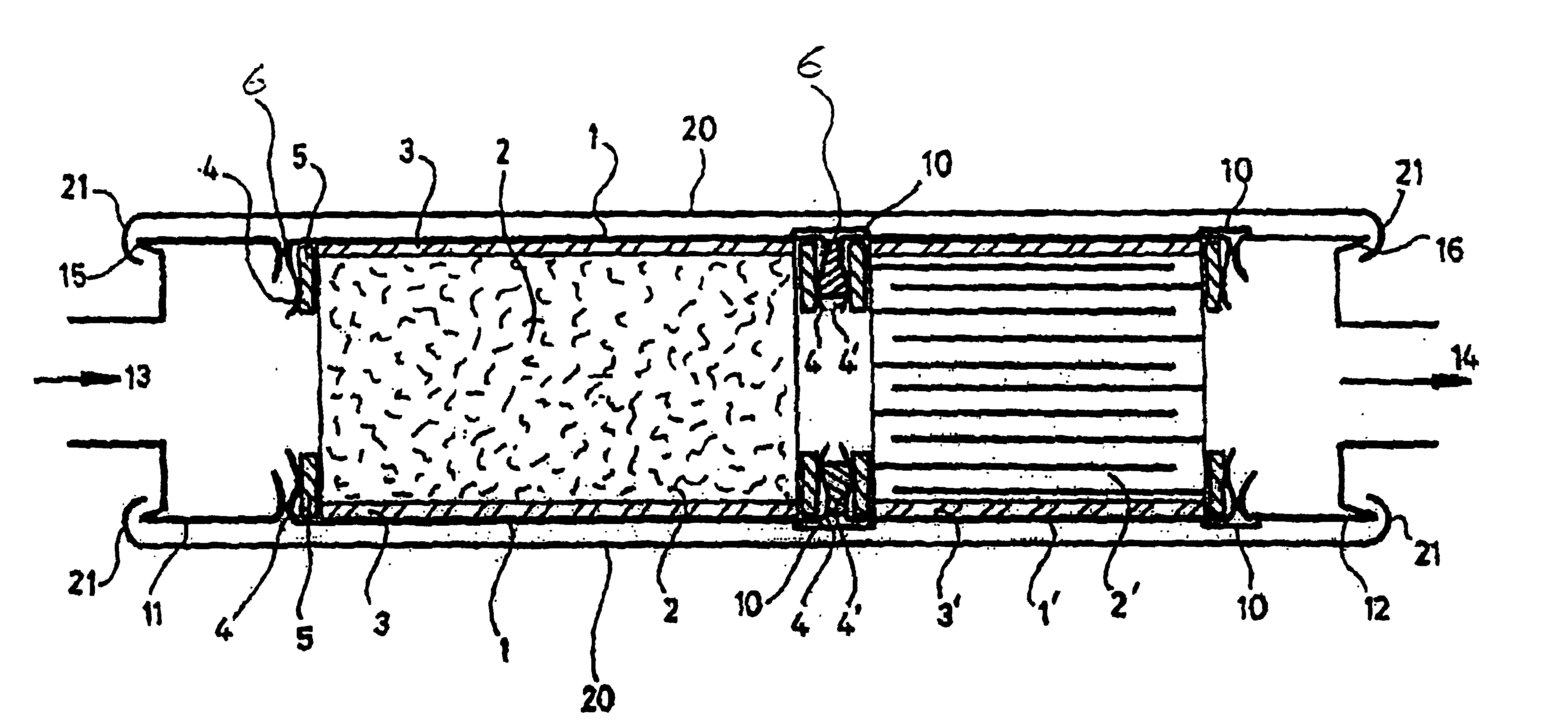
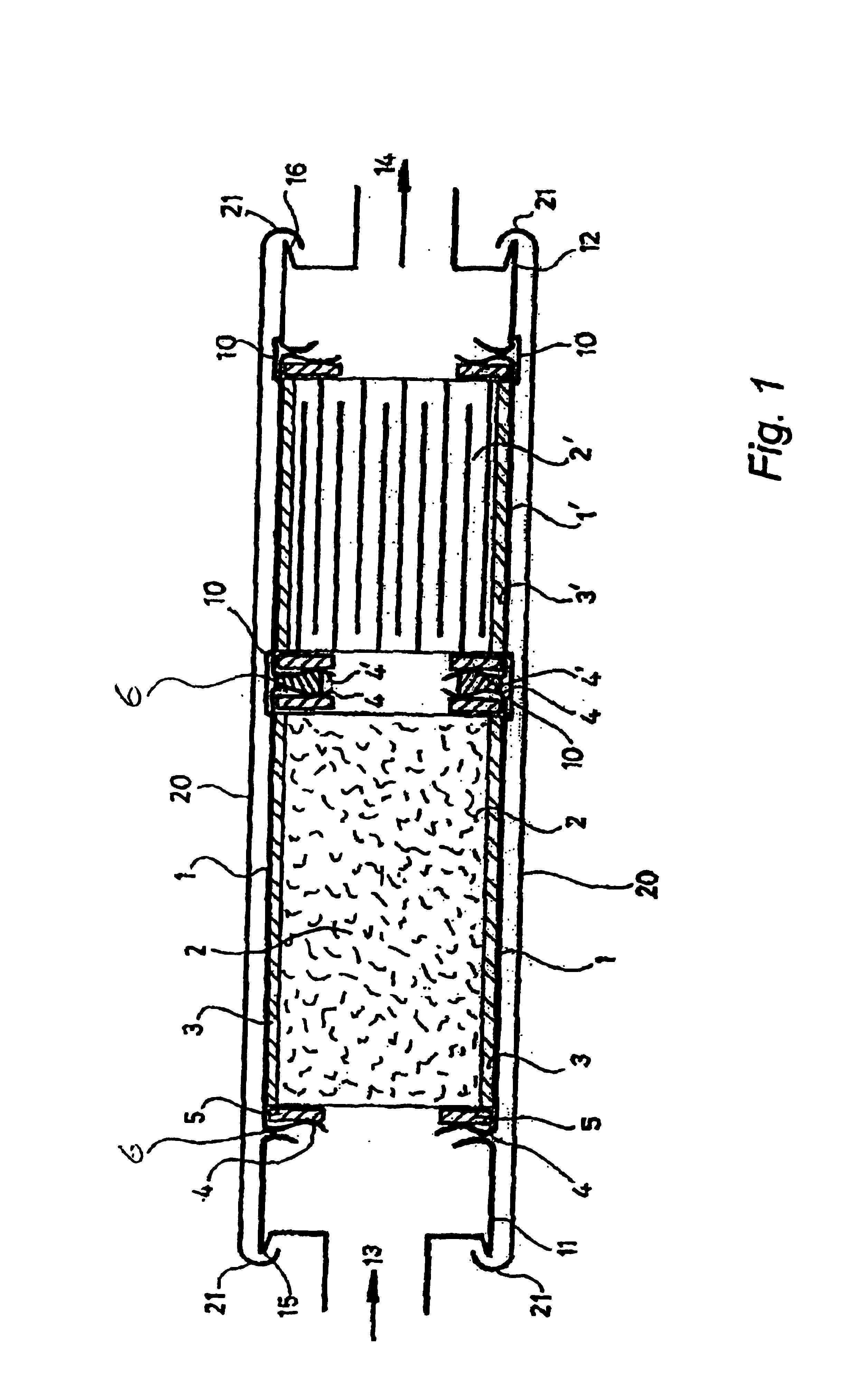
The silencer comprises two or more modules each comprising a tubular body member 1, containing a cylindrical treatment element 2 surrounded by a sleeve 3 of the shock absorbent material sold under the Trade Mark Interam. For example, one tubular body member contains a foraminous ceramic frit core carrying a Rhodium / Platinum catalyst deposited on the exposed surfaces within the core; another tubular body member contains a cast ceramic filter element having a plurality of axial passages therein alternatively open to each end of the element and being formed from a porous ceramic so that the flow path for gas through the filter element is tortuous.

Each end of the tubular member 1 is formed with an in-folded flange 4, which provides an annular internal shoulder 6 within the bore of member 1 against which the terminal portion of the treatment element 2 engages. The flange may be circumferentially continuous or intermittent. It will usually be desired to provide an annular ring 5 of metal ...


PUM

PropertyMeasurementUnit
angleaaaaaaaaaa
anglesaaaaaaaaaa
axial movementaaaaaaaaaa

Abstract

The invention provides apparatus for treating a gas stream, notably a silencer assembly for use to treat the exhaust gasses from an internal combustion engine, which apparatus comprises a plurality of compartments within which one or more treatments are to be performed on a gas stream passing through the compartment, and through which the gas stream is to flow sequentially, characterised in that:
  • a. At least two of said compartments each comprises a tubular body member containing or carrying a treatment element which is restrained against axial movement relative to the body member; and
  • b. The tubular body members of the adjacent compartments are provided with radially outwardly and/or inwardly extending terminal flanges, at least some of which flanges provide a shoulder against which the opposing terminal portion of the adjacent compartment bears so as to form an axially extending structure comprising at least two compartments in axial or coaxial relationship to one another; and
  • c. One or more clamping members which extend axially over substantially the length of the said structure and act upon the axial structure to secure the two adjacent compartments together in gas-tight engagement by an axial clamping action.

Description

TECHNICAL FIELDThe present invention relates to an apparatus, notably to a gas treatment chamber for treating the exhaust gases of an internal combustion engine for motor vehicles and other applications.BACKGROUND TO THE INVENTIONDiesel engine exhaust gases contain a number of noxious gases, such a nitrogen oxides, sulphur oxides and carbon oxides, as well as un-burnt hydrocarbons, carbon and other particles. The amount of sulphur oxides in the exhaust gases is dependent primarily upon the sulphur in the fuel and is controlled by the quality of the initial crude oil and the refining techniques used in the preparation of the fuel. However, the other materials can be treated so as to render them less obnoxious.It is therefore common practice to pass the exhaust gases through a silencer assembly which contains one or more treatment chambers containing a catalytic converter in which the lower nitrogen oxides are converted to NO2. The carbon particles and droplets of un-burnt hydrocarbon...

Claims


Application Information

Patent Timeline
Patent Type & Authority Patents(United States)
IPC IPC(8): F01N3/28F01N3/021F01N3/20F01N3/033F01N7/00F01N7/02F01N1/10B01D46/00B01D53/94F01N3/02F01N3/24F01N13/02
CPCF01N3/0211F01N3/0335F01N3/206F01N3/2839F01N13/0097F01N3/2867F01N3/2885F01N3/2857F01N2470/18F01N2610/02
Inventor GAULT, ANTHONY JOHNMILLES, DAVID HERBERT
Owner GAULT ANTHONY JOHN
Why Eureka
Try Eureka