Wind energy capturing device for moving vehicles

a technology of wind energy capturing and moving vehicles, which is applied in the direction of machines/engines, renewable energy generation, electric generator control, etc., can solve the problems of wind drag, limited driving range, and detrimental to the overall efficiency of the vehicle, so as to reduce drag

Inactive Publication Date: 2005-01-04
VU THOMAS H
View PDF18 Cites 130 Cited by
  • Summary
  • Abstract
  • Description
  • Claims
  • Application Information

AI Technical Summary

Benefits of technology

The present invention is a wind energy-capturing device for moving vehicles having a wind turbine mounted on the roof of the moving vehicle in an area exposed to the wind force generate by the moving vehicle. The rotating output shaft of the wind turbine is connected to an electric generator, either directly or by belt and pulley or other system. The wind turbine, generator, and any storage battery system are preferably mounted on the roof of the tractor of a trailer and underneath and to the rear of a modified wind deflector similar to those already in use on truck tractor roofs to reduce drag from the front of the trailer exposed above the tractor roof. The generator and battery system can be mounted at locations other than the roof of the tractor. The truck may be hybrid-electric vehicle driven by at least one electric motor in combination with a battery system and a gasoline or diesel engine.

Problems solved by technology

The greatest challenge with wind turbines as a reliable source of energy is that they depend on the quantity and quality of the wind.
This wind causes “wind drag,” and is usually detrimental to the overall efficiency of the vehicle.
The greatest challenges for such electric vehicles include the fact that the battery system must be recharged when battery system power is exhausted, and the driving range is limited, due to limited storage capacity in its battery system.
The prevailing wind force is therefore detrimental to the efficiency of the moving vehicles.

Method used


Image

  • Wind energy capturing device for moving vehicles
  • Wind energy capturing device for moving vehicles
  • Wind energy capturing device for moving vehicles

Examples


Embodiment Construction

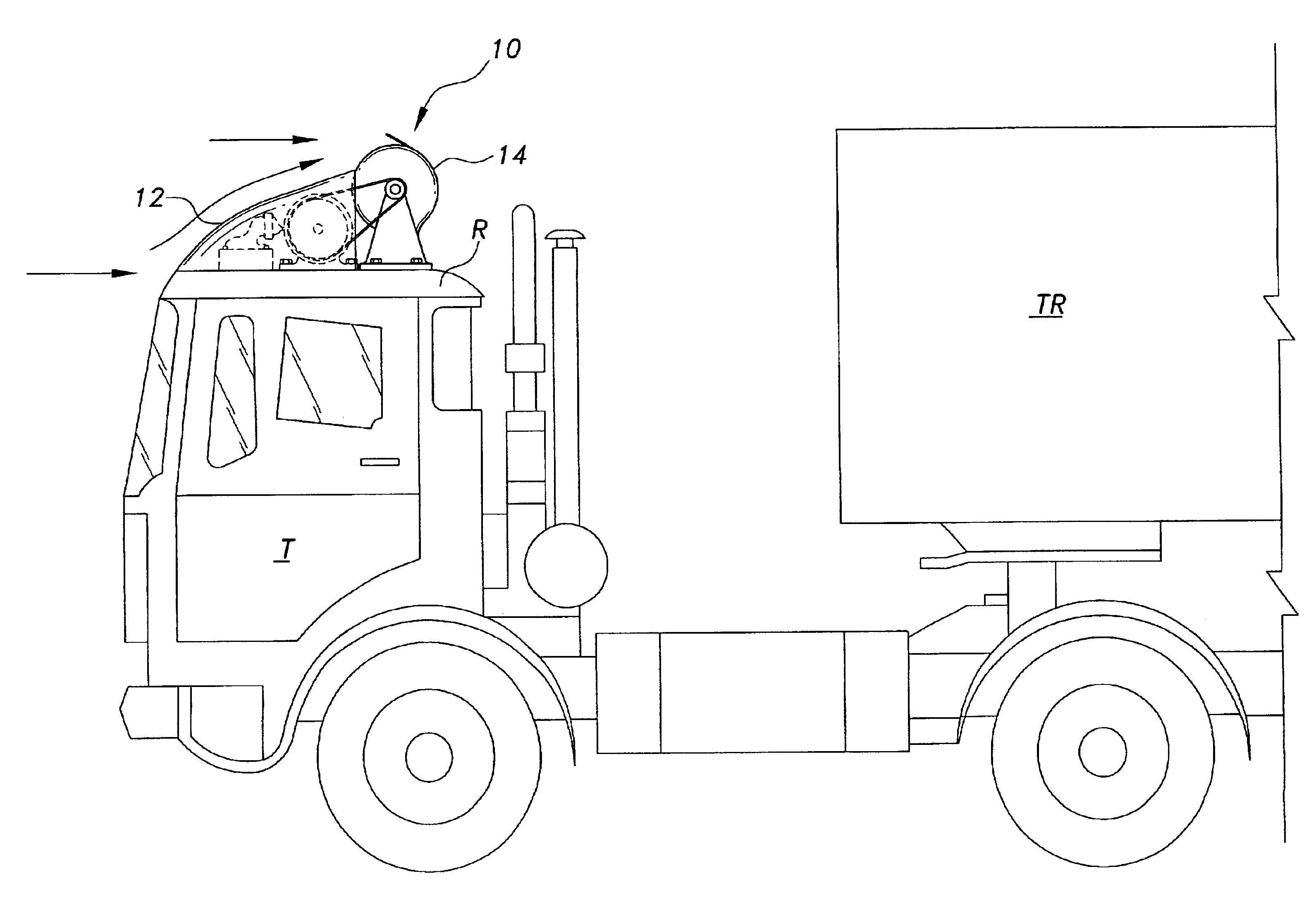
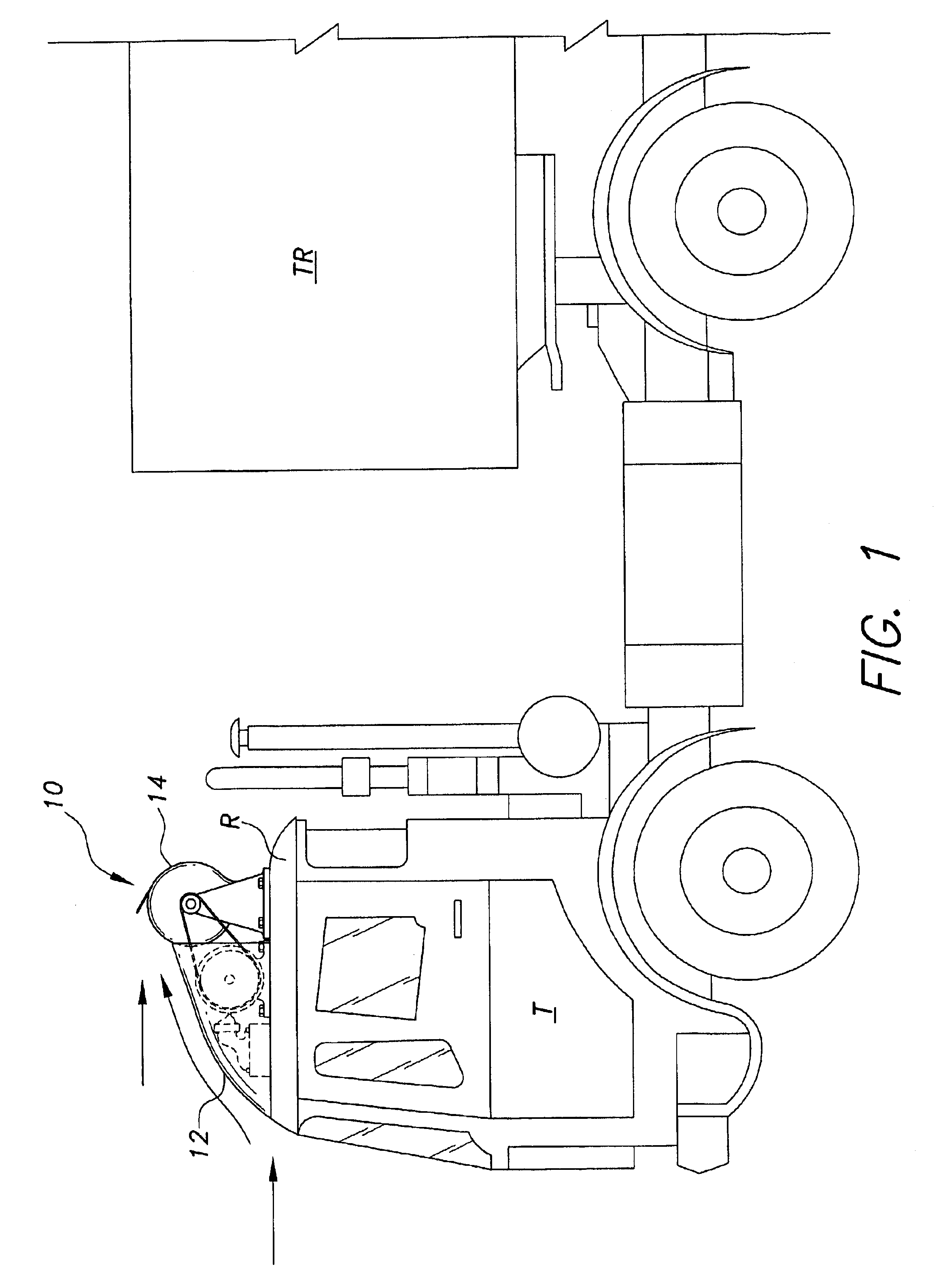
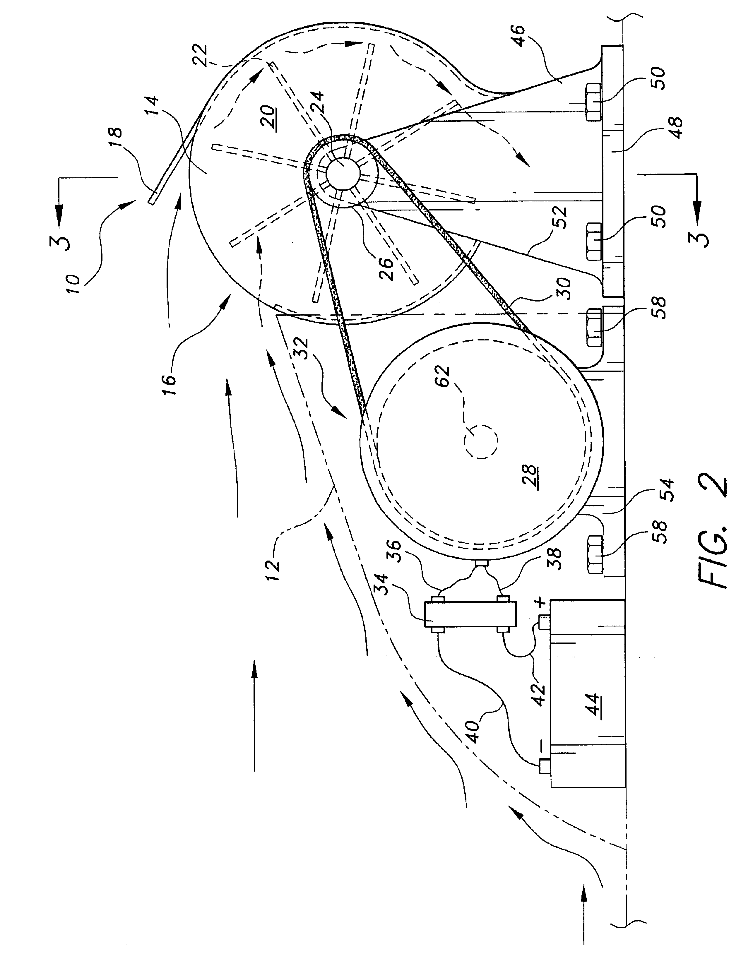
The present invention is a wind turbine powered electrical power generator for installation on the roof of a moving vehicle such as a truck cab or tractor. The invention takes advantage of the powerful wind force generated by the vehicle moving on the road at moderate to high speed impinging against the wind deflector mounted on the truck cab or tractor. This otherwise “wasted” wind energy is captured and directed to the face area of a rotor blade, rotating a turbine, which, in turn, drives a generator to generate electricity. The truck may be hybrid-electric vehicle driven by at least one electric motor in combination with a battery system and a gasoline or diesel engine.

To generate the same amount of energy, the rotor-blade diameter of the wind turbine of the present invention can be of much smaller size, due to the prevailing high wind velocity, and fairly constant wind speed developed in the slip stream of a moving vehicle as compared to convention stationary wind turbines which...


PUM


Abstract

A wind energy capturing device for moving vehicles including a wind turbine powered electrical power generator for installation on the roof of a moving vehicle such as a truck cab or tractor. The invention takes advantage of the powerful wind force generated by the vehicle moving on the road at moderate to high speed impinging against the wind deflector mounted on the truck cab or tractor. This otherwise “wasted” wind energy is captured and directed to the face area of the rotor blade, rotating the turbine, which, in turn, drives the generator to generate electricity. The electrical energy may be stored in a battery system and used to drive the motors of an electric vehicle or hybrid-electric vehicle.

Description

BACKGROUND OF THE INVENTION1. Field of the InventionThe present invention relates to electric power generation for vehicles. More particularly, the present invention relates to wind turbines mounted on moving vehicles for converting the wind energy into electricity for storage in a battery system or use by the vehicle.2. Description of the Related ArtWind turbines are typically mounted on wind towers in areas known to have high wind velocity. Various configurations of wind turbines are designed to convert wind energy into electrical power for use in homes and industries.The greatest challenge with wind turbines as a reliable source of energy is that they depend on the quantity and quality of the wind. Depending on the design, wind speed must maintain a certain minimum velocity to overcome friction of moving parts. Even in the best geographical areas, average wind speed is only in the range of 18 to 47 kph. To justify the projects, and generate adequate return on investment, the size...

Claims


Application Information

Patent Timeline
Patent Type & Authority Patents(United States)
IPC IPC(8): B60L8/00F03D11/04F03D11/00F03D3/00
CPCB60K6/48F03D3/002F03D9/002F03D11/04B60L8/006B60K16/00Y02T10/648B60K2016/006F05B2240/941F05B2260/4021Y02E10/728Y02E10/74Y02T10/6221Y02T10/646Y02T10/7083Y02T10/90F03D13/20F03D9/25F03D9/11F03D9/32Y02T10/62Y02T10/64Y02T10/7072Y02E70/30
Inventor VU, THOMAS H.
Owner VU THOMAS H
Why Eureka
Try Eureka