
Apparatus and method for making an optical fiber amplifier

a technology of optical fiber amplifier and amplifier, which is applied in the field of optical fiber telecommunication systems, can solve the problems of many possible failure points, and high cost of optical fiber amplifier

Inactive Publication Date: 2005-01-04
II VI DELAWARE INC
View PDF38 Cites 35 Cited by
  • Summary
  • Abstract
  • Description
  • Claims
  • Application Information

AI Technical Summary

Problems solved by technology

Because the manufacture of optical amplifiers typically requires optically connecting various sections of fiber, many points of failure are possible.
Accordingly, any failure in a network generally requires shutting down the network to access one or more of the failed components.
Troubleshooting the cause of a network failure is time consuming, hence, the cost of a network failure can nm into hundreds of thousands, if not millions, of dollars in lost communications.
Such individualized amplifier manufacturing techniques have been one of the contributing factors in the high cost of optical fiber amplifiers.
When a newly assembled optical fiber amplifier fails to meet the desired technical specifications and needs reworking, such failures lead to significant delays in the production process.
In addition, when manufacturing more than one type of amplifier for a network system, such delays in reworking are multiplied and can result in significant monetary loss due to the precise assembly and testing procedures utilized.

Method used


Image

  • Apparatus and method for making an optical fiber amplifier
  • Apparatus and method for making an optical fiber amplifier
  • Apparatus and method for making an optical fiber amplifier

Examples


Embodiment Construction

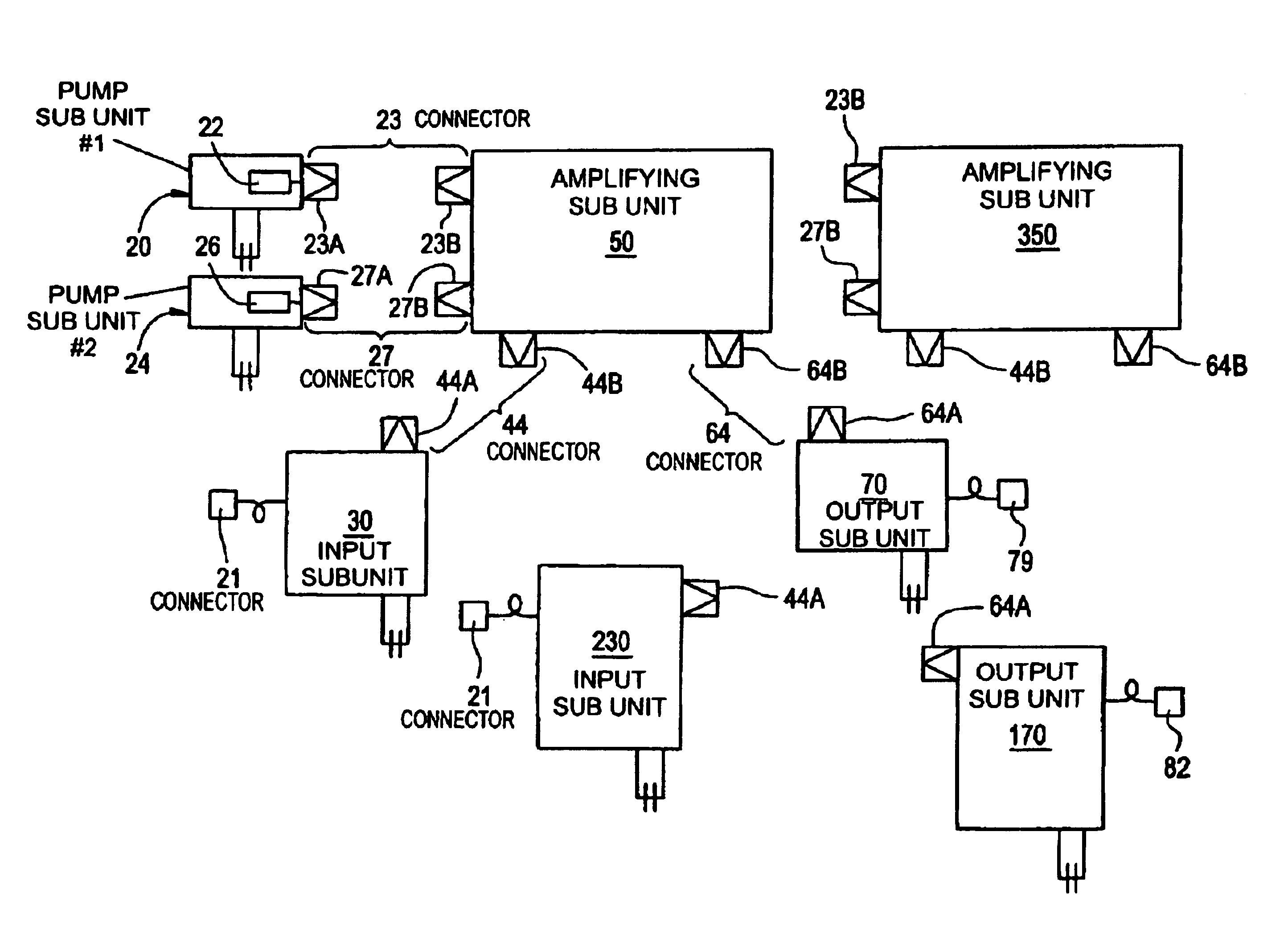
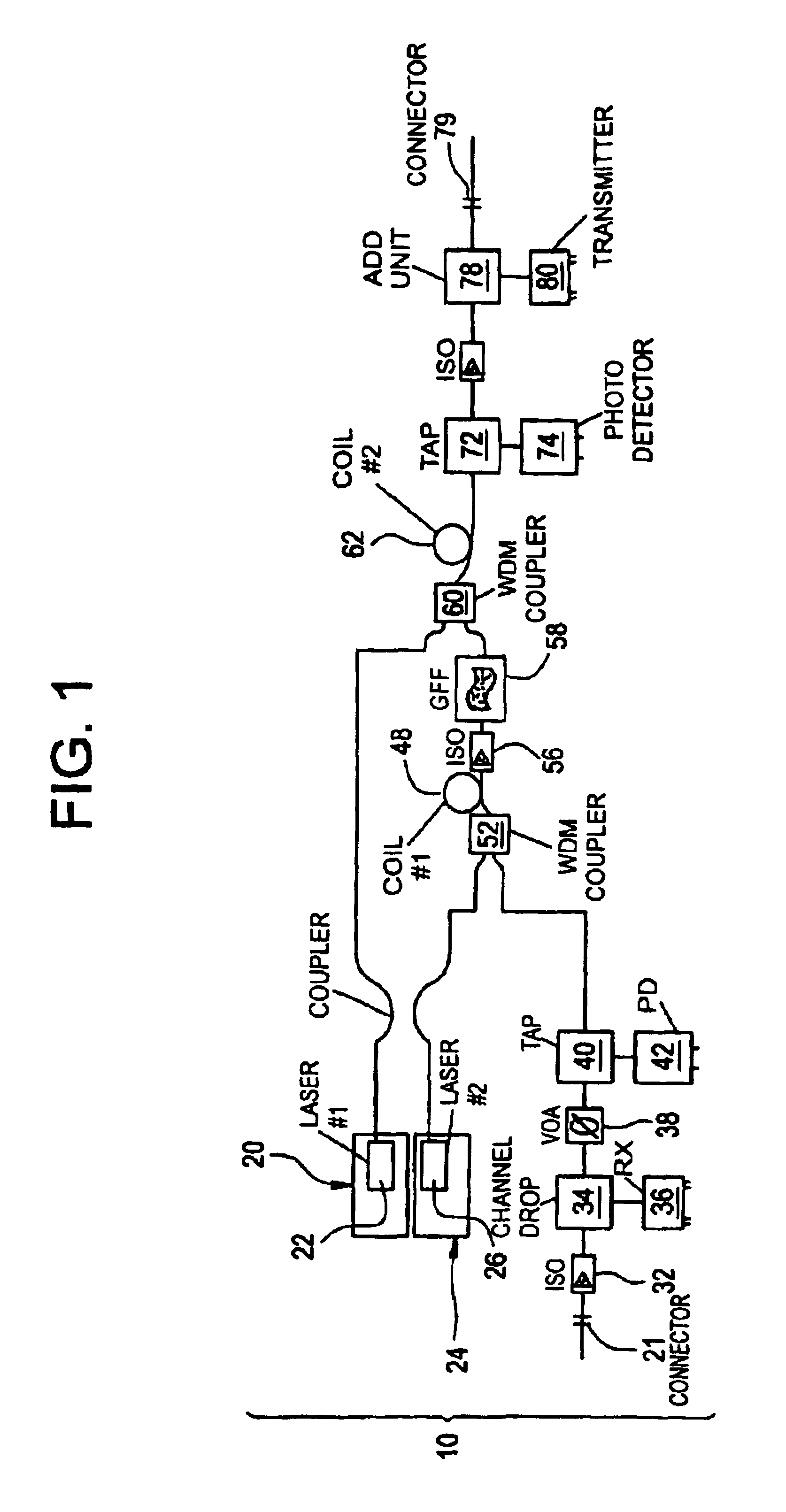
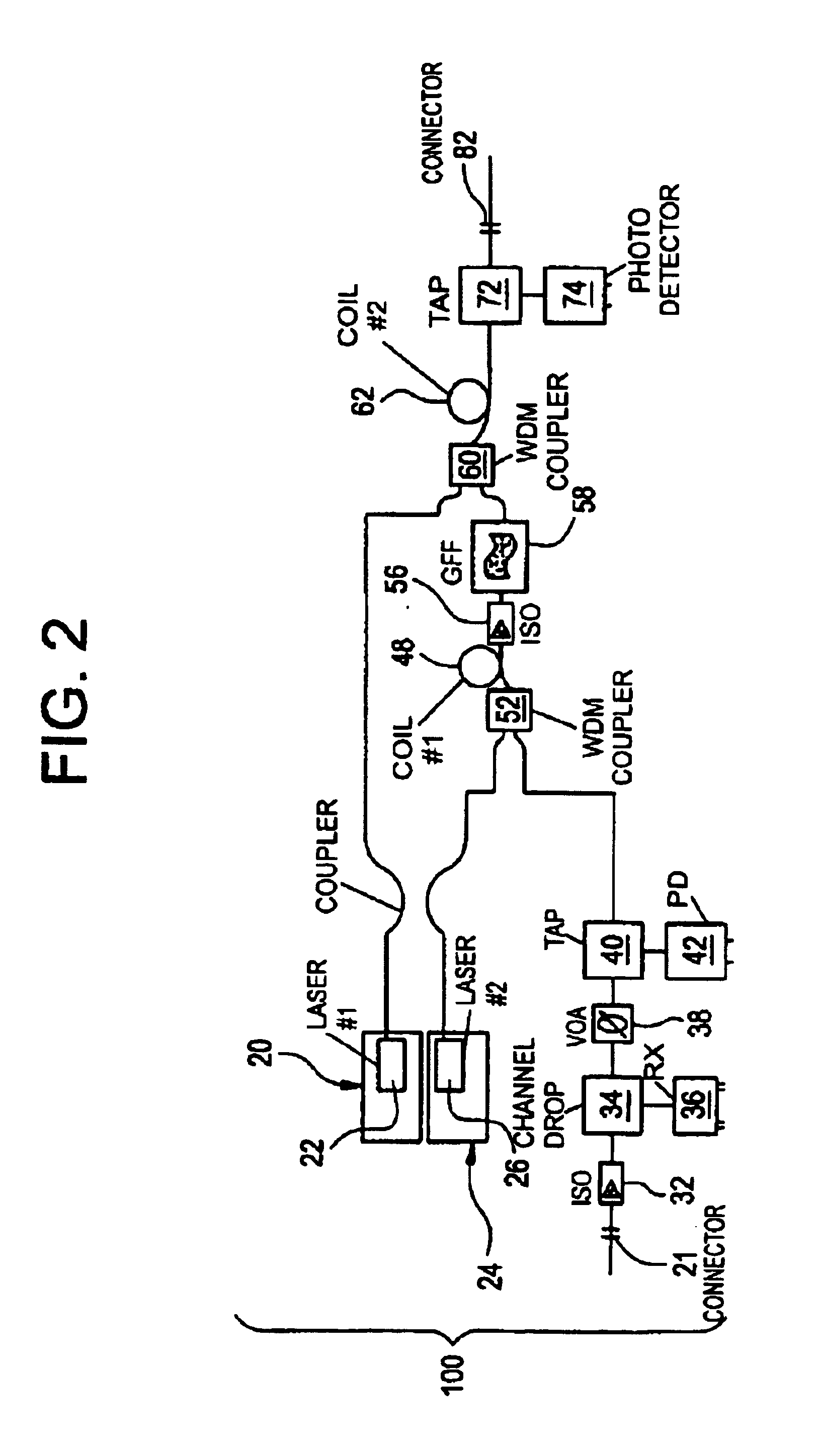
hematic illustration of the multi-channel output amplifier of FIG. 3 showing the various similar and dissimilar fiber splices in accordance with the present invention.

[0018]FIG. 13 is a schematic illustration of the multi-channel input amplifier of FIG. 4 showing the various similar and dissimilar fiber splices in accordance with the present invention.

DESCRIPTION OF THE PREFERRED EMBODIMENTS

[0019]The invention disclosed herein generally embodies the provision of an optical fiber amplifier constructed of a plurality of detachable pluggable sub-units. The invention also provides a method of making an optical fiber amplifier by plugging together at least three, preferably, four pluggable sub-units. Although, the description will discuss the manufacture of a family of four optical fiber amplifiers that are used in a metropolitan area network, the invention provides a method of making any one of a family of N optical fiber amplifiers by plugging together at least three, preferably, four ...


PUM


Abstract

An apparatus and method for making n different types of optical amplifiers on one manufacturing line, n being equal to 2 or more. The method includes providing a supply of at least four functional groups of subunits for each of the circuits which comprise each of the optical amplifiers to be made, where at least one functional group contains at least n different types of sub-units, and where each of the sub-units in three of the functional groups includes a pluggable optical connector half and where each of the sub-units of the fourth of the functional groups includes three pluggable optical connector halves. The method further includes selecting a specific sub-unit from each of the four functional groups and plugging together each of the selected subunits to form an optical amplifier having the desired specification.

Description

FIELD OF THE INVENTION[0002]The present invention relates to optical fiber telecommunication systems and, in particular, to a rare earth doped optical fiber amplifier employed in such systems.BACKGROUND INFORMATION[0003]An optical transmission signal fades with distance when traveling through any type of optical fiber telecommunication system and, thus, needs amplification. In this regard, optical fiber amplifiers are used to transform a weak input optical transmission signal into a strong output optical transmission signal. Optical fiber amplifiers contain optical fibers with cores doped with certain rare earth elements, such as, erbium, that amplify light at certain wavelengths. The amplified wavelengths depend primarily on the rare earth dopant and on the fiber composition. Typically, a rare earth doped optical fiber amplifier utilizes a light source from an external laser, such as a semiconductor pump laser, to excite the dopant atoms in the optical fiber from a ground state to ...

Claims


Application Information

Patent Timeline
Patent Type & Authority Patents(United States)
IPC IPC(8): H01S3/06H01S3/067G02B6/00H01S3/10H01S3/23
CPCH01S3/06704
Inventor JAKOBSON, PAUL A.MURPHY, EDWARD F.WETHERILL, TODD M.
Owner II VI DELAWARE INC
Learn More