Magnetic random access memory

Inactive Publication Date: 2005-01-04
SK HYNIX INC
View PDF12 Cites 6 Cited by
  • Summary
  • Abstract
  • Description
  • Claims
  • Application Information

AI Technical Summary

Benefits of technology

A magnetic random access memory (MRAM) configured to achieve high integration and to simplify the whole process by using a ground line connected to a source terminal as a write line instead of forming a special write line is described herein. The MRAM includes: a substrate including a source region, a drain region and a gate region; a word line formed on the gate region; a source contact formed on the source region; a drain contact formed on the drain region; a common line electrically connected to the upper portion of the source contact by a first conta

Problems solved by technology

Accordingly, there is a problem in the conventional MRAM as the size of the MRAM cell increases.
Further, there is a need for a proce

Method used


Image

  • Magnetic random access memory
  • Magnetic random access memory
  • Magnetic random access memory

Examples


Example

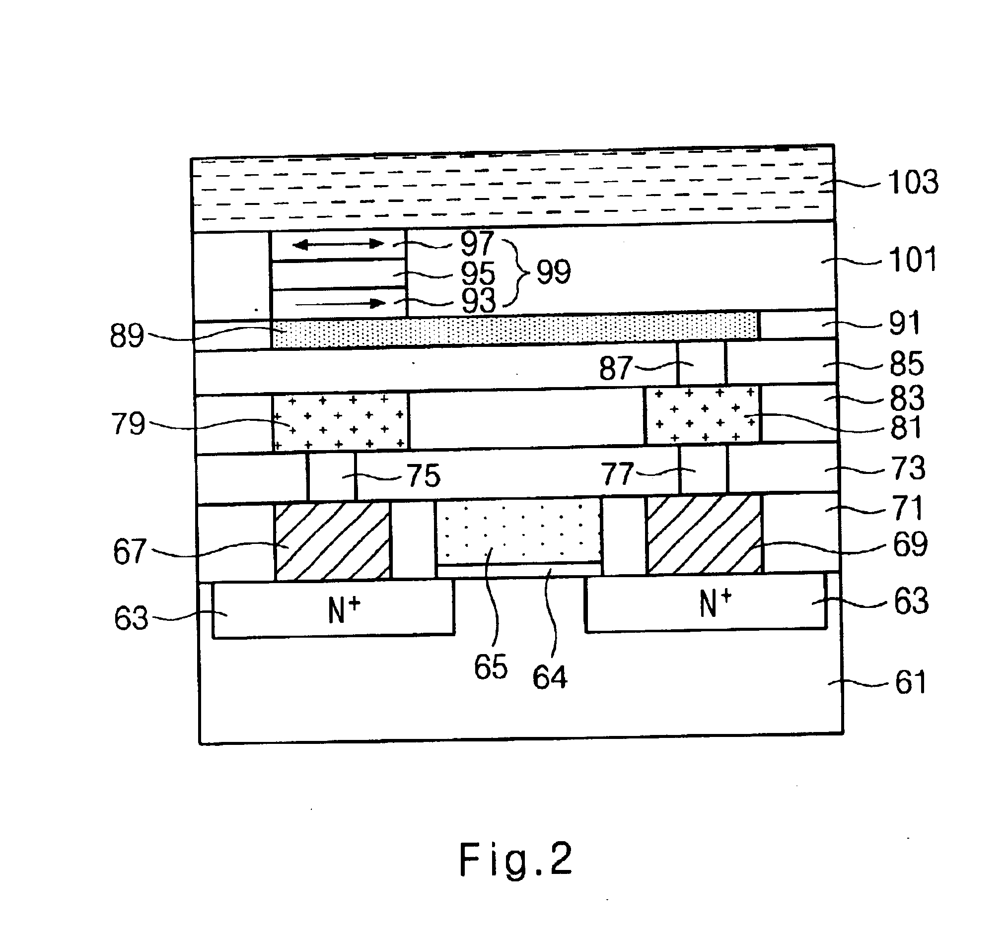
The present disclosure will be described in detail with reference to the accompanying drawings. A structure of the MRAM to write data on an MTJ element by using a common line and a bit line is described herein. Referring to FIG. 2, a source region and a drain region are defined by two N+ regions 63 separately formed on a P-substrate 61. A source contact 67 is formed on the N+ region 63 corresponding to the source region, and a drain contact 69 is formed on the N+ region 63 corresponding to the drain region. The source contact 67 and the drain contact 69 are formed in the same layer as a first interlayer insulating film 71. A gate electrode 65 is separately formed between the source contact 67 and the drain contact 69. A gate oxide film 64 is formed below the gate electrode 65.

A first contact plug 75 and a second contact plug 77 are formed on the source contact 67 and the drain contact 69, respectively. A common line 79 and a metal line 81 are formed on the first contact plug 75 and ...


PUM


Abstract

A magnetic random access memory (MRAM) using a common line is described herein. An MTJ element is positioned on the common line of the MRAM. The common line connected to a source of a transistor transmits a ground level voltage for reading data and supplies a current for writing data.

Description

TECHNICAL FIELDThe present disclosure relates generally to semiconductor memory, and more particularly, to a magnetic random access memory (MRAM).BACKGROUNDMost of the semiconductor memory manufacturing companies have developed the MRAM using a ferromagnetic material as one of the next generation memory devices. The MRAM is a memory device to store information by forming multi-layer ferromagnetic thin films. The stored information can be read by sensing current variations according to a magnetization direction of the respective thin film. The MRAM operates at a high speed, reduces power consumption, allows high integration density by the special properties of the magnetic thin film, and performs a nonvolatile memory operation such as a flash memory.The MRAM embodies memory devices by using the fact that the spin influences electron transmission. First, the MRAM using a giant magneto resistive (GMR) phenomenon utilizes the fact that resistance is larger when spin directions are diffe...

Claims


Application Information

Patent Timeline
IPC IPC(8): G11C11/16G11C11/02G11C11/15H01L21/8246H01L27/105H01L27/22H01L43/08
CPCB82Y10/00H01L27/228G11C11/16G11C11/1659G11C11/1675G11C11/1673G11C11/1657H10B61/22H01L27/105
Inventor JANG, IN WOOPARK, YOUNG JINLEE, KYE NAMKIM, CHANG SHUKKYUNG, HEE
Owner SK HYNIX INC
Why Eureka
Try Eureka